HP Spectre 13-v100 Maintenance and Service Guide - Page 44
Remove the three Phillips PM2.0×3.0 screws, Keyboard cable
 |
View all HP Spectre 13-v100 manuals
Add to My Manuals
Save this manual to your list of manuals |
Page 44 highlights
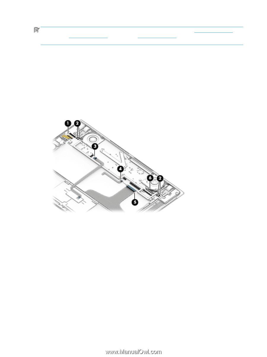
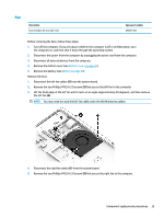
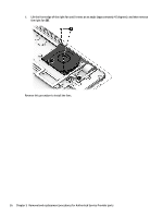
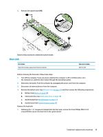
NOTE: When replacing the system board, be sure to remove the solid-state drive (Heat sink on page 39), WLAN module (Heat sink on page 39), and heat sink (Heat sink on page 39) from the defective system board and install them on the replacement system board. Remove the system board: 1. Disconnect the following cables from the system board: (1) WLAN module (2) Left and right fan cables (3) TouchPad cable (4) Keyboard backlight cable (5) Keyboard cable (6) Display panel cable 2. Remove the three Phillips PM2.0×3.0 screws (1) that secure the system board to the computer. 3. Swing the front edge of the system board up and back so you can access the RTC battery cable (2). 4. Disconnect the RTC battery cable (3) from the system board. 38 Chapter 5 Removal and replacement procedures for Authorized Service Provider parts
-
 1
1 -
2
-
3
-
4
-
5
-
6
-
7
-
8
-
9
-
10
-
11
-
12
-
13
-
14
-
15
-
16
-
17
-
18
-
19
-
20
-
21
-
22
-
23
-
24
-
25
-
26
-
27
-
28
-
29
-
30
-
31
-
32
-
33
-
34
-
35
-
36
-
37
-
38
-
 39
39 -
 40
40 -
 41
41 -
 42
42 -
 43
43 -
 44
44 -
 45
45 -
 46
46 -
 47
47 -
 48
48 -
 49
49 -
50
-
51
-
52
-
53
-
54
-
55
-
56
-
57
-
58
-
59
-
60
-
61
 |
 |