HP Spectre 13-v100 Maintenance and Service Guide - Page 46
and on the system board, shown in the following image.
 |
View all HP Spectre 13-v100 manuals
Add to My Manuals
Save this manual to your list of manuals |
Page 46 highlights
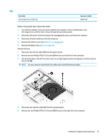
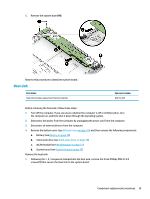
2. Remove the heat sink (2). NOTE: Due to the adhesive quality of the thermal material located between the heat sink and the system board components, it may be necessary to move the heat sink from side to side to detach it. NOTE: The thermal material must be thoroughly cleaned from the surfaces of the heat sink and the system board each time the heat sink is removed. Replacement thermal material is included with the heat sink and system board spare part kits. Thermal paste is used on the heat sink (1) and on the system board (2) as shown in the following image. Reverse this procedure to install the heat sink. 40 Chapter 5 Removal and replacement procedures for Authorized Service Provider parts
-
 1
1 -
2
-
3
-
4
-
5
-
6
-
7
-
8
-
9
-
10
-
11
-
12
-
13
-
14
-
15
-
16
-
17
-
18
-
19
-
20
-
21
-
22
-
23
-
24
-
25
-
26
-
27
-
28
-
29
-
30
-
31
-
32
-
33
-
34
-
35
-
36
-
37
-
38
-
39
-
40
-
 41
41 -
 42
42 -
 43
43 -
 44
44 -
 45
45 -
 46
46 -
 47
47 -
 48
48 -
 49
49 -
 50
50 -
 51
51 -
52
-
53
-
54
-
55
-
56
-
57
-
58
-
59
-
60
-
61
 |
 |

2.
Remove the heat sink
(2)
.
NOTE:
Due to the adhesive quality of the thermal material located between the heat sink and
the system board components, it may be necessary to move the heat sink from side to side to detach it.
NOTE:
The thermal material must be thoroughly cleaned from the surfaces of the heat sink and the system
board each time the heat sink is removed. Replacement thermal material is included with the heat sink and
system board spare part kits. Thermal paste is used on the heat sink
(1)
and on the system board
(2)
as
shown in the following image.
Reverse this procedure to install the heat sink.
40
Chapter 5
Removal and replacement procedures for Authorized Service Provider parts