HP Spectre 13-v100 Maintenance and Service Guide - Page 45
Heat sink, Solid-state drive see
 |
View all HP Spectre 13-v100 manuals
Add to My Manuals
Save this manual to your list of manuals |
Page 45 highlights
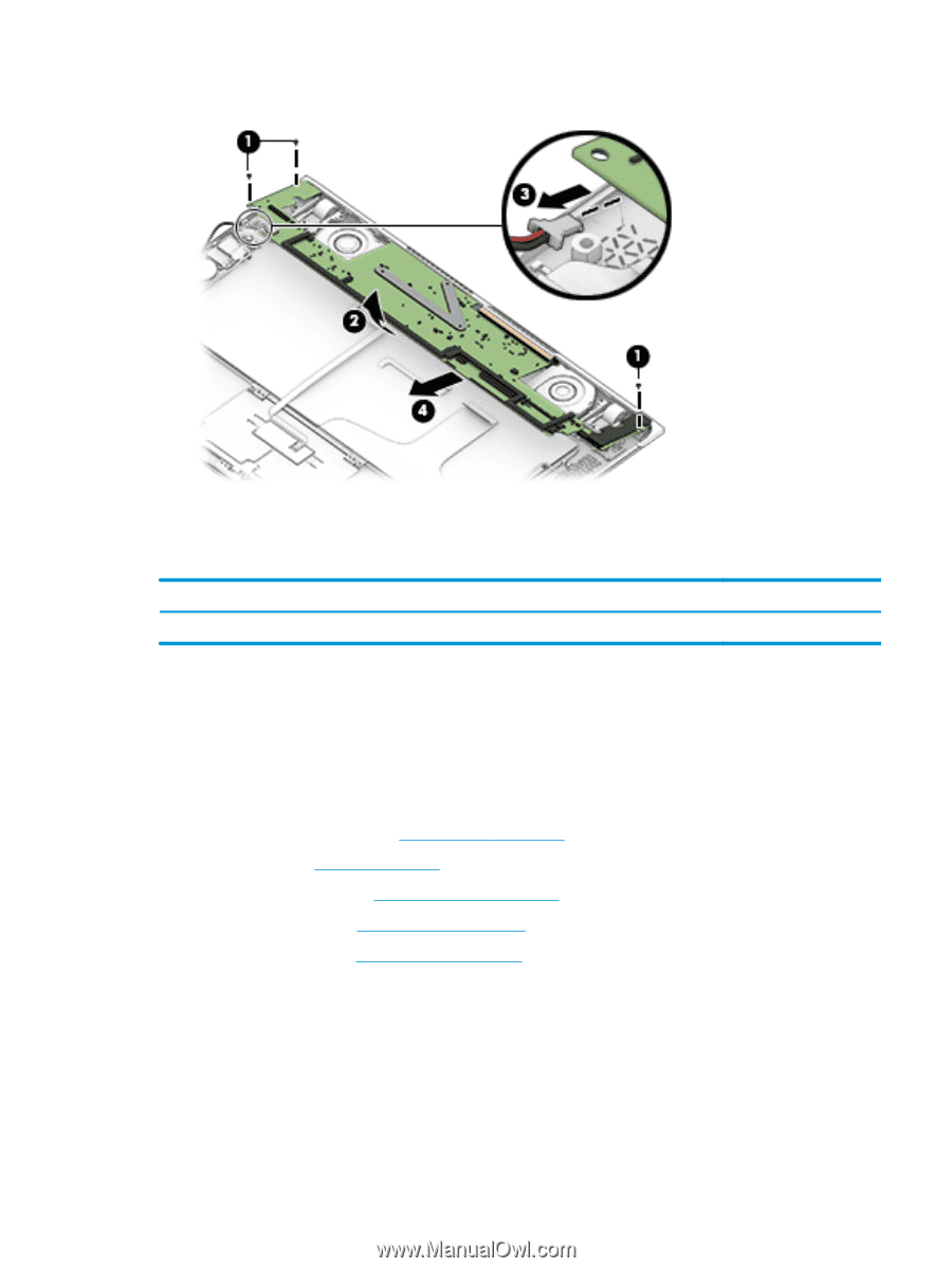
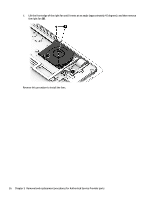
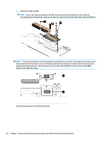
5. Remove the system board (4). Reverse this procedure to install the system board. Heat sink Description Heat sink (includes replacement thermal material) Spare part number 854752-001 Before removing the heat sink, follow these steps: 1. Turn off the computer. If you are unsure whether the computer is off or in Hibernation, turn the computer on, and then shut it down through the operating system. 2. Disconnect the power from the computer by unplugging the power cord from the computer. 3. Disconnect all external devices from the computer. 4. Remove the bottom cover (see Bottom cover on page 26), and then remove the following components: a. Battery (see Battery on page 28) b. Solid-state drive (see Solid-state drive on page 30) c. WLAN module (see WLAN module on page 31) d. System board (see System board on page 37) Remove the heat sink: 1. Following the 1, 2, 3 sequence stamped into the heat sink, remove the three Phillips PM2.0×3.0 screws (1) that secure the heat sink to the system board. Component replacement procedures 39
-
 1
1 -
2
-
3
-
4
-
5
-
6
-
7
-
8
-
9
-
10
-
11
-
12
-
13
-
14
-
15
-
16
-
17
-
18
-
19
-
20
-
21
-
22
-
23
-
24
-
25
-
26
-
27
-
28
-
29
-
30
-
31
-
32
-
33
-
34
-
35
-
36
-
37
-
38
-
39
-
 40
40 -
 41
41 -
 42
42 -
 43
43 -
 44
44 -
 45
45 -
 46
46 -
 47
47 -
 48
48 -
 49
49 -
 50
50 -
51
-
52
-
53
-
54
-
55
-
56
-
57
-
58
-
59
-
60
-
61
 |
 |