HP StorageWorks 1510i HP StorageWorks 1510i Modular Smart Array maintenance an - Page 24
Slot diagram LEDs, Located on the rear of the MSA
 |
View all HP StorageWorks 1510i manuals
Add to My Manuals
Save this manual to your list of manuals |
Page 24 highlights
Slot diagram LEDs Located on the rear of the MSA, the slot diagram provides information about MSA modules. 1. 2-Port Ethernet iSCSI module (for the controller in slot 2) 2. SCSI I/O module (bus 3) 3. SCSI I/O module (bus 2) 4. Fan module 1 5. Fan module 2 6. 2-Port Ethernet iSCSI module (for the controller in slot 2) 7. SCSI I/O module (bus 1) 8. SCSI I/O module (bus 0) 9. Power supply 1 10. Power supply 2 newpage pi 24 System components and LEDs
-
 1
1 -
2
-
3
-
4
-
5
-
6
-
7
-
8
-
9
-
10
-
11
-
12
-
13
-
14
-
15
-
16
-
17
-
18
-
 19
19 -
 20
20 -
 21
21 -
 22
22 -
 23
23 -
 24
24 -
 25
25 -
 26
26 -
 27
27 -
 28
28 -
 29
29 -
30
-
31
-
32
-
33
-
34
-
35
-
36
-
37
-
38
-
39
-
40
-
41
-
42
-
43
-
44
-
45
-
46
-
47
-
48
-
49
-
50
-
51
-
52
-
53
-
54
-
55
-
56
-
57
-
58
-
59
-
60
-
61
-
62
-
63
-
64
-
65
-
66
-
67
-
68
-
69
-
70
-
71
-
72
-
73
-
74
-
75
-
76
-
77
-
78
-
79
-
80
-
81
-
82
-
83
-
84
 |
 |

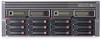
Slot diagram LEDs
Located on the rear of the MSA, the slot diagram provides information about MSA modules.
1. 2–Port Ethernet iSCSI module (for the controller in slot 2)
2. SCSI I/O module (bus 3)
3. SCSI I/O module (bus 2)
4. Fan module 1
5. Fan module 2
6. 2–Port Ethernet iSCSI module (for the controller in slot 2)
7. SCSI I/O module (bus 1)
8. SCSI I/O module (bus 0)
9. Power supply 1
10. Power supply 2
newpage pi
24
System components and LEDs