HP Workstation i2000 hp workstation i2000 processor installation (a6037-90060) - Page 22
E-PAC Installation
 |
View all HP Workstation i2000 manuals
Add to My Manuals
Save this manual to your list of manuals |
Page 22 highlights
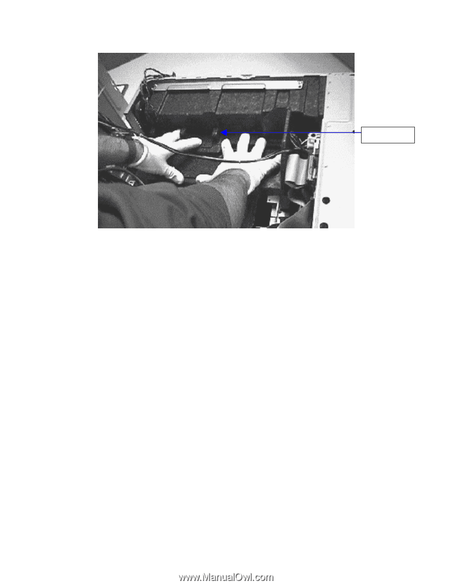
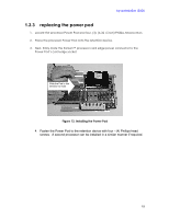
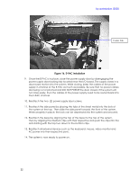
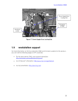
hp workstation i2000 Center Tab Figure 16. E-PAC Installation 9. Once the E-PAC is in place, close the power supply door by disengaging the power supply door-locking tab located near the I/O board. The supply closes in a downward motion into the system. While closing, keep the cables of the power supply in channel of the E-PAC as much as possible. Be sure that no power cables are being cut or pinched and DO NOT FORCE the door closed. If the system will not close easily, then the cables of the power supply need to be routed back into the E-PAC channel. 10. Reattach the two- (2) power supply door screws. 11. Reattach the side panel by placing the tabs of the sheet metal into the slots of the system at the top. Then slide the side panel towards the front of the system. When properly in place, the lock can be depressed into the system and secured. 12. Reattach the bezel by aligning the top of the bezel to the top of the system. Then by aligning the interlock clips with their respective slots push the clips into the slots starting with the top two down to the bottom clips. 13. Reattach all external devices such as the keyboard, mouse, video monitor and AC power into their respective ports. 14. The system is now ready to power on. 22
-
 1
1 -
2
-
3
-
4
-
5
-
6
-
7
-
8
-
9
-
10
-
11
-
12
-
13
-
14
-
15
-
16
-
 17
17 -
 18
18 -
 19
19 -
 20
20 -
 21
21 -
 22
22 -
 23
23 -
 24
24
 |
 |