HP Workstation i2000 hp workstation i2000 processor installation (a6037-90060) - Page 3

HP Workstation i2000 Manual

Page 3 highlights

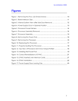
Figures hp workstation i2000 Figure 1. Removing the Four- (4) Chassis Screws 10 Figure 2. Bezel Interlock Clips 11 Figure 3. Internal System View after Side Door Removal 12 Figure 4. Power Supply Door in Opened Position 13 Figure 5. Processor Power Harness 14 Figure 6. Processor Assembly Removal 14 Figure 7. Processor Assembly 15 Figure 8. Removing the Power Pod 16 Figure 9. Removing the Processor 16 Figure 10. Replacing the Processor 17 Figure 11. Properly Seating the Processor 18 Figure 12. Top View of Processor and Cross-Torque Pattern 18 Figure 13. Installing the Power Pod 19 Figure 14. Correct Reinstallation of E-PAC 21 Figure 15. E-PAC Inserted over Memory Cards 21 Figure 16. E-PAC Installation 22 Figure 17. Power Supply Door Locking Tab 23 3

  • 1
  • 2
  • 3
  • 4
  • 5
  • 6
  • 7
  • 8
  • 9
  • 10
  • 11
  • 12
  • 13
  • 14
  • 15
  • 16
  • 17
  • 18
  • 19
  • 20
  • 21
  • 22
  • 23
  • 24

hp workstation i2000
3
Figures
Figure 1. Removing the Four- (4) Chassis Screws
................................................
10
Figure 2. Bezel Interlock Clips
................................................................................
11
Figure 3. Internal System View after Side Door Removal
...................................
12
Figure 4. Power Supply Door in Opened Position
...............................................
13
Figure 5. Processor Power Harness
.......................................................................
14
Figure 6. Processor Assembly Removal
................................................................
14
Figure 7. Processor Assembly
................................................................................
15
Figure 8. Removing the Power Pod
......................................................................
16
Figure 9. Removing the Processor
........................................................................
16
Figure 10
.
Replacing the Processor
......................................................................
17
Figure 11. Properly Seating the Processor
............................................................
18
Figure 12. Top View of Processor and Cross-Torque Pattern
.............................
18
Figure 13. Installing the Power Pod
.......................................................................
19
Figure 14. Correct Reinstallation of E-PAC
...........................................................
21
Figure 15. E-PAC Inserted over Memory Cards
...................................................
21
Figure 16. E-PAC Installation
..................................................................................
22
Figure 17. Power Supply Door Locking Tab
.........................................................
23