HP dx2390 Service Reference Guide: HP Compaq dx2390 Business PC - Page 20
Serial and Parallel ATA Drive Guidelines and Features, SATA Hard Drives
 |
View all HP dx2390 manuals
Add to My Manuals
Save this manual to your list of manuals |
Page 20 highlights
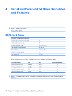
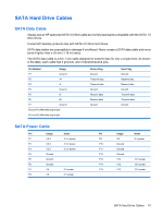
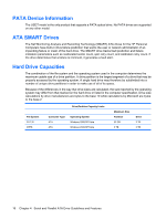
4 Serial and Parallel ATA Drive Guidelines and Features NOTE: Serial ATA = SATA Parallel ATA = PATA SATA Hard Drives Serial ATA Hard Drive Characteristics Number of pins/conductors in data cable Number of pins in power cable Maximum data cable length Data interface voltage differential Drive voltages Jumpers for configuring drive Data transfer rate 7/7 15 39.37 in (100 cm) 400-700 mV 3.3 V, 5 V, 12 V N/A 3.0 Gb/s SATA connectors on the system board are color coded to make identification easier. SATA Identification Primary channel, device 0 Primary channel, device 1 Secondary channel, device 0 Secondary channel, device 1 Color Dark blue Light Blue White Orange Port SATA 0 SATA 2 SATA 1 SATA 3 Attachment Sequence 1 4 2 3 NOTE: If there is an error on the application of the attach rules, a POST error message may be displayed. 14 Chapter 4 Serial and Parallel ATA Drive Guidelines and Features
-
 1
1 -
2
-
3
-
4
-
5
-
6
-
7
-
8
-
9
-
10
-
11
-
12
-
13
-
14
-
 15
15 -
 16
16 -
 17
17 -
 18
18 -
 19
19 -
 20
20 -
 21
21 -
 22
22 -
 23
23 -
 24
24 -
 25
25 -
26
-
27
-
28
-
29
-
30
-
31
-
32
-
33
-
34
-
35
-
36
-
37
-
38
-
39
-
40
-
41
-
42
-
43
-
44
-
45
-
46
-
47
-
48
-
49
-
50
-
51
-
52
-
53
-
54
-
55
-
56
-
57
-
58
-
59
-
60
-
61
-
62
-
63
-
64
-
65
-
66
-
67
-
68
-
69
-
70
-
71
-
72
-
73
-
74
-
75
-
76
-
77
-
78
-
79
-
80
-
81
-
82
-
83
-
84
-
85
-
86
-
87
-
88
-
89
-
90
-
91
-
92
-
93
-
94
-
95
-
96
-
97
-
98
-
99
-
100
-
101
-
102
-
103
-
104
 |
 |