HP dx2390 Service Reference Guide: HP Compaq dx2390 Business PC - Page 48
Drives
 |
View all HP dx2390 manuals
Add to My Manuals
Save this manual to your list of manuals |
Page 48 highlights
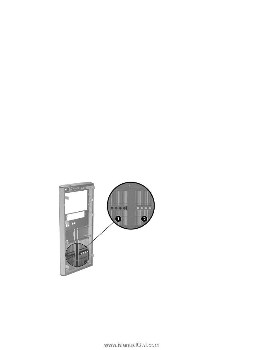
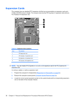
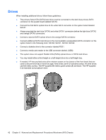
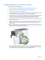
Drives When installing additional drives, follow these guidelines: ● The primary Serial ATA (SATA) hard drive must be connected to the dark blue primary SATA connector on the system board labeled SATA0. ● Connect the first SATA optical drive to the white SATA connector on the system board labeled SATA1. ● Always populate the dark blue SATA0 and white SATA1 connectors before the light blue SATA2 and orange SATA3 connectors. ● Connect a second SATA optical drive to the orange SATA3 connector. ● Connect additional SATA hard drives to the next available (unpopulated) SATA connector on the system board in the following order: SATA0, SATA1, SATA3, SATA2. ● Connect a diskette drive to the connector labeled FDD1. ● Connect a media card reader to the USB connector labeled JUSB2. ● The system does not support Parallel ATA (PATA) optical drives or PATA hard drives. ● You may install either a third-height or a half-height drive into a half-height bay. ● If needed, HP has provided extra drive retainer screws on the interior of the front bezel that are used to secure the drives in the drive cage. Hard drives use 6-32 standard screws. All other drives use M3 metric screws. The HP-supplied M3 metric guide screws (1) are black. The HP-supplied 6-32 standard screws (2) are silver. 42 Chapter 6 Removal and Replacement Procedures Microtower (MT) Chassis
-
 1
1 -
2
-
3
-
4
-
5
-
6
-
7
-
8
-
9
-
10
-
11
-
12
-
13
-
14
-
15
-
16
-
17
-
18
-
19
-
20
-
21
-
22
-
23
-
24
-
25
-
26
-
27
-
28
-
29
-
30
-
31
-
32
-
33
-
34
-
35
-
36
-
37
-
38
-
39
-
40
-
41
-
42
-
 43
43 -
 44
44 -
 45
45 -
 46
46 -
 47
47 -
 48
48 -
 49
49 -
 50
50 -
 51
51 -
 52
52 -
 53
53 -
54
-
55
-
56
-
57
-
58
-
59
-
60
-
61
-
62
-
63
-
64
-
65
-
66
-
67
-
68
-
69
-
70
-
71
-
72
-
73
-
74
-
75
-
76
-
77
-
78
-
79
-
80
-
81
-
82
-
83
-
84
-
85
-
86
-
87
-
88
-
89
-
90
-
91
-
92
-
93
-
94
-
95
-
96
-
97
-
98
-
99
-
100
-
101
-
102
-
103
-
104
 |
 |