HP dx2390 Service Reference Guide: HP Compaq dx2390 Business PC - Page 64
Power Switch/LED Assembly
 |
View all HP dx2390 manuals
Add to My Manuals
Save this manual to your list of manuals |
Page 64 highlights
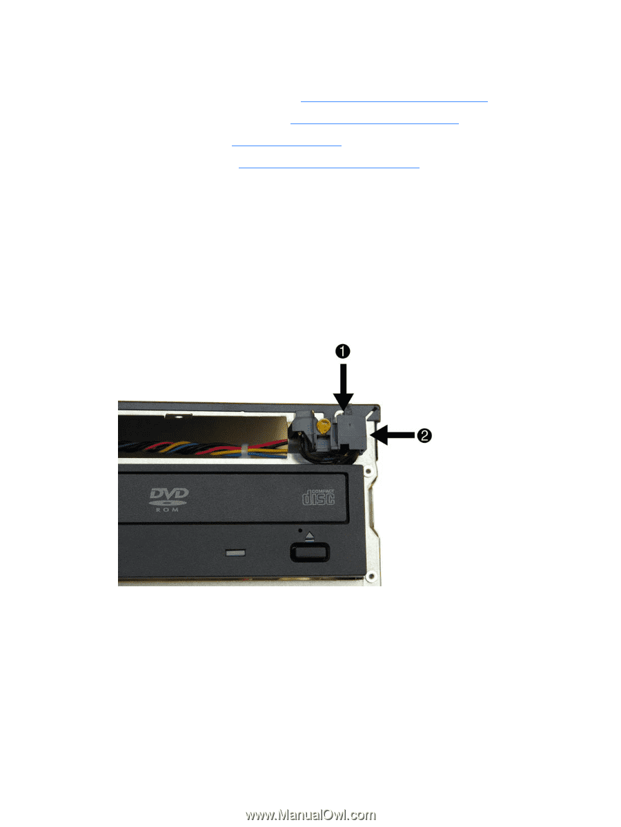
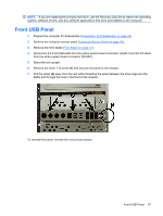
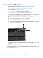
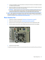
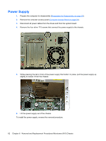
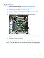
Power Switch/LED Assembly 1. Prepare the computer for disassembly (Preparation for Disassembly on page 26). 2. Remove the computer access panel (Computer Access Panel on page 30). 3. Remove the front bezel (Front Bezel on page 31). 4. Remove the optical drive (Removing an Optical Drive on page 46). 5. Disconnect the cable from the black system board connector labeled JFP1. 6. Remove the cable from the metal clamps on the side of the drive cage. This step may require a flat blade screwdriver to lift the clamps enough to remove the cable. 7. To remove the power button assembly, perform the following steps simultaneously: a. On the right side of the assembly, press down on the top tab (1). b. Press in on the tab on the right side of the assembly (2). c. While pressing the two tabs, pull the assembly away from the chassis enough to loosen the tabs from their slots in the chassis. 8. Pull the assembly away from the chassis while threading the wire through the hole in the front of the chassis. 9. Remove the assembly from the chassis. To reinstall the assembly, reverse the removal procedures. Be sure to route the cable through the metal clamps on the side of the drive cage. 58 Chapter 6 Removal and Replacement Procedures Microtower (MT) Chassis
-
 1
1 -
2
-
3
-
4
-
5
-
6
-
7
-
8
-
9
-
10
-
11
-
12
-
13
-
14
-
15
-
16
-
17
-
18
-
19
-
20
-
21
-
22
-
23
-
24
-
25
-
26
-
27
-
28
-
29
-
30
-
31
-
32
-
33
-
34
-
35
-
36
-
37
-
38
-
39
-
40
-
41
-
42
-
43
-
44
-
45
-
46
-
47
-
48
-
49
-
50
-
51
-
52
-
53
-
54
-
55
-
56
-
57
-
58
-
 59
59 -
 60
60 -
 61
61 -
 62
62 -
 63
63 -
 64
64 -
 65
65 -
 66
66 -
 67
67 -
 68
68 -
 69
69 -
70
-
71
-
72
-
73
-
74
-
75
-
76
-
77
-
78
-
79
-
80
-
81
-
82
-
83
-
84
-
85
-
86
-
87
-
88
-
89
-
90
-
91
-
92
-
93
-
94
-
95
-
96
-
97
-
98
-
99
-
100
-
101
-
102
-
103
-
104
 |
 |