HP dx2390 Service Reference Guide: HP Compaq dx2390 Business PC - Page 67
Rear Chassis Fan
 |
View all HP dx2390 manuals
Add to My Manuals
Save this manual to your list of manuals |
Page 67 highlights
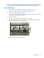
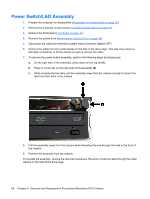
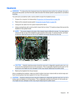
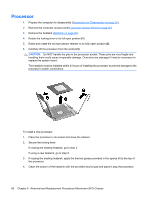
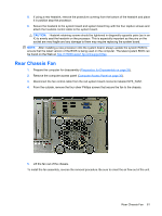
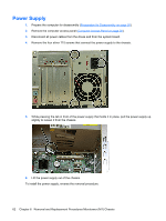
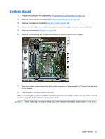
5. If using a new heatsink, remove the protective covering from the bottom of the heatsink and place it in position atop the processor. 6. Secure the heatsink to the system board and system board tray with the four captive screws and attach the heatsink control cable to the system board. CAUTION: Heatsink retaining screws should be tightened in diagonally opposite pairs (as in an X) to evenly seat the heatsink on the processor. This is especially important as the pins on the socket are very fragile and any damage to them may require replacing the system board. NOTE: After installing a new processor onto the system board, always update the system ROM to ensure that the latest version of the BIOS is being used on the computer. The latest system BIOS can be found on the Web at: http://h18000.www1.hp.com/support/files. Rear Chassis Fan 1. Prepare the computer for disassembly (Preparation for Disassembly on page 26). 2. Remove the computer access panel (Computer Access Panel on page 30). 3. Disconnect the fan control cable from the red system board connector labeled SYS_FAN1. 4. From the outside, remove the four silver Phillips screws that secure the fan to the chassis. 5. Lift the fan out of the chassis. To install the fan assembly, reverse the removal procedure. Be sure to orient the air flow out of the unit. Rear Chassis Fan 61
-
 1
1 -
2
-
3
-
4
-
5
-
6
-
7
-
8
-
9
-
10
-
11
-
12
-
13
-
14
-
15
-
16
-
17
-
18
-
19
-
20
-
21
-
22
-
23
-
24
-
25
-
26
-
27
-
28
-
29
-
30
-
31
-
32
-
33
-
34
-
35
-
36
-
37
-
38
-
39
-
40
-
41
-
42
-
43
-
44
-
45
-
46
-
47
-
48
-
49
-
50
-
51
-
52
-
53
-
54
-
55
-
56
-
57
-
58
-
59
-
60
-
61
-
 62
62 -
 63
63 -
 64
64 -
 65
65 -
 66
66 -
 67
67 -
 68
68 -
 69
69 -
 70
70 -
 71
71 -
 72
72 -
73
-
74
-
75
-
76
-
77
-
78
-
79
-
80
-
81
-
82
-
83
-
84
-
85
-
86
-
87
-
88
-
89
-
90
-
91
-
92
-
93
-
94
-
95
-
96
-
97
-
98
-
99
-
100
-
101
-
102
-
103
-
104
 |
 |