HP dx2390 Service Reference Guide: HP Compaq dx2390 Business PC - Page 57
System Board Drive Connections, on USB connector on the system board labeled JUSB2.
 |
View all HP dx2390 manuals
Add to My Manuals
Save this manual to your list of manuals |
Page 57 highlights
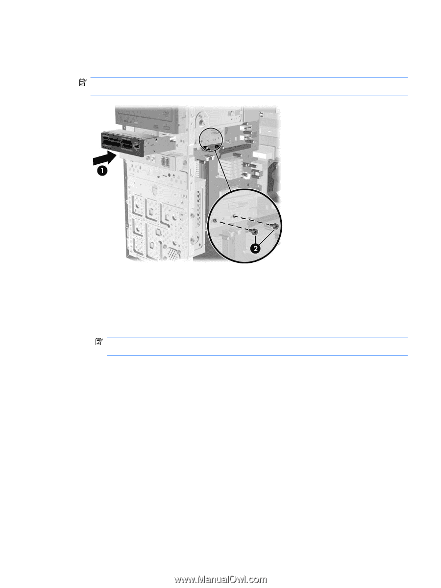
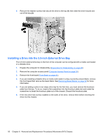
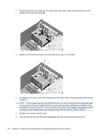
7. Slide the drive in through the front of the chassis (1) until the bezel on the drive is evenly aligned with the computer front bezel and install the M3 metric retainer screws (2) as shown in the illustration below. NOTE: Extra drive retainer screws are provided on the interior of the front bezel if needed. The M3 metric retainer screws for diskette drives or media card readers are black. 8. Connect the appropriate drive cables: a. If installing a diskette drive, connect the power and data cables to the rear of the drive and connect the other end of the data cable to the connector on the system board labeled FDD1. b. If installing a media card reader, connect the USB cable from the media card reader to the USB connector on the system board labeled JUSB2. NOTE: Refer to System Board Drive Connections on page 44 for an illustration of the system board drive connectors. 9. Replace the front bezel and access panel. 10. Lock any security devices that were disengaged when the access panel was removed. Drives 51
-
 1
1 -
2
-
3
-
4
-
5
-
6
-
7
-
8
-
9
-
10
-
11
-
12
-
13
-
14
-
15
-
16
-
17
-
18
-
19
-
20
-
21
-
22
-
23
-
24
-
25
-
26
-
27
-
28
-
29
-
30
-
31
-
32
-
33
-
34
-
35
-
36
-
37
-
38
-
39
-
40
-
41
-
42
-
43
-
44
-
45
-
46
-
47
-
48
-
49
-
50
-
51
-
 52
52 -
 53
53 -
 54
54 -
 55
55 -
 56
56 -
 57
57 -
 58
58 -
 59
59 -
 60
60 -
 61
61 -
 62
62 -
63
-
64
-
65
-
66
-
67
-
68
-
69
-
70
-
71
-
72
-
73
-
74
-
75
-
76
-
77
-
78
-
79
-
80
-
81
-
82
-
83
-
84
-
85
-
86
-
87
-
88
-
89
-
90
-
91
-
92
-
93
-
94
-
95
-
96
-
97
-
98
-
99
-
100
-
101
-
102
-
103
-
104
 |
 |