HP dx2390 Service Reference Guide: HP Compaq dx2390 Business PC - Page 83
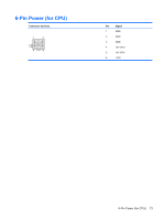
DVI Connector
 |
View all HP dx2390 manuals
Add to My Manuals
Save this manual to your list of manuals |
Page 83 highlights
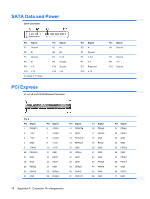
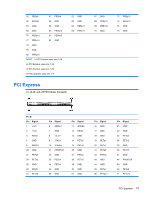
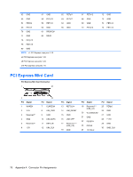
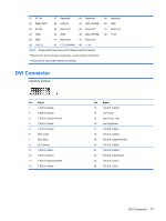
31 PETn0 37 Reserved* 43 Reserved* 32 SMB_DATA 38 USB_D+ 44 LED_WLAN# 33 PETp0 39 Reserved* 45 Reserved* 34 GND 40 GND 46 LED_WPAN# 36 GND 41 Reserved* 47 Reserved* 36 USB_D- 42 LED_WWAN# 48 +1.5V NOTE: *Reserved for future second PCI Express LAN (if needed) **Reserved for future wireless coexistence control interface (if needed) ***Reserved for future UIM interface (if needed) 49 Reserved* 50 GND 51 Reserved* 52 +3.3V DVI Connector Connector and Icon Pin Signal 1 T.M.D.S. Data2- 2 T.M.D.S. Data2+ 3 T.M.D.S. Data2/4 Shield 4 T.M.D.S. Data4- 5 T.M.D.S. Data4+ 6 DDC Clock 7 DDC Data 8 No Connect 9 T.M.D.S. Data1- 10 T.M.D.S. Data1+ 11 T.M.D.S. Data1/3 Shield 12 T.M.D.S. Data3- Pin Signal 13 T.M.D.S. Data3+ 14 +5V Power 15 Ground (for +5V) 16 Hot Pug Detect 17 T.M.D.S. Data0- 18 T.M.D.S. Data0+ 19 T.M.D.S. Data0/5 Shield 20 T.M.D.S. Data5- 21 T.M.D.S. Data5+ 22 T.M.D.S. Data Shield 23 T.M.D.S. Clock+ 24 T.M.D.S. Clock- DVI Connector 77
-
 1
1 -
2
-
3
-
4
-
5
-
6
-
7
-
8
-
9
-
10
-
11
-
12
-
13
-
14
-
15
-
16
-
17
-
18
-
19
-
20
-
21
-
22
-
23
-
24
-
25
-
26
-
27
-
28
-
29
-
30
-
31
-
32
-
33
-
34
-
35
-
36
-
37
-
38
-
39
-
40
-
41
-
42
-
43
-
44
-
45
-
46
-
47
-
48
-
49
-
50
-
51
-
52
-
53
-
54
-
55
-
56
-
57
-
58
-
59
-
60
-
61
-
62
-
63
-
64
-
65
-
66
-
67
-
68
-
69
-
70
-
71
-
72
-
73
-
74
-
75
-
76
-
77
-
 78
78 -
 79
79 -
 80
80 -
 81
81 -
 82
82 -
 83
83 -
 84
84 -
 85
85 -
 86
86 -
 87
87 -
 88
88 -
89
-
90
-
91
-
92
-
93
-
94
-
95
-
96
-
97
-
98
-
99
-
100
-
101
-
102
-
103
-
104
 |
 |