HP rp7420 Installation Guide, Fifth Edition - HP 9000 rp7420 Server - Page 62
Safety Ground Reference Check, Safety Ground Verification
 |
View all HP rp7420 manuals
Add to My Manuals
Save this manual to your list of manuals |
Page 62 highlights
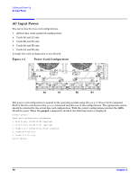
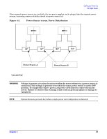
Cabling and Power Up Voltage Check Safety Ground Verification This measures the voltage level between B0 and A0. The measurement is taken between ground pins of the two power cords. See Figure 4-4 for ground reference points when performing this measurement. Figure 4-4 Safety Ground Reference Check Step 1. Measure the voltage between B0 and A0. Take the AC voltage down to the lowest scale on the volt meter. Step 2. Insert one probe into the ground pin for B0. Step 3. Insert the other probe into the ground pin for A0. Step 4. Verify that the measurement is between 0-5 V AC. If the measurement is 5 V or greater, escalate the situation. Do not attempt to plug the power cords into the HP 9000 rp7420 Server. 62 Chapter 4
-
 1
1 -
2
-
3
-
4
-
5
-
6
-
7
-
8
-
9
-
10
-
11
-
12
-
13
-
14
-
15
-
16
-
17
-
18
-
19
-
20
-
21
-
22
-
23
-
24
-
25
-
26
-
27
-
28
-
29
-
30
-
31
-
32
-
33
-
34
-
35
-
36
-
37
-
38
-
39
-
40
-
41
-
42
-
43
-
44
-
45
-
46
-
47
-
48
-
49
-
50
-
51
-
52
-
53
-
54
-
55
-
56
-
 57
57 -
 58
58 -
 59
59 -
 60
60 -
 61
61 -
 62
62 -
 63
63 -
 64
64 -
 65
65 -
 66
66 -
 67
67 -
68
-
69
-
70
-
71
-
72
-
73
-
74
-
75
-
76
-
77
-
78
-
79
-
80
 |
 |

Chapter 4
Cabling and Power Up
Voltage Check
62
Safety Ground Verification
This measures the voltage level between B0 and A0. The measurement is taken between ground
pins of the two power cords. See Figure 4-4 for ground reference points when performing this
measurement.
Figure 4-4 Safety Ground Reference Check
Step 1.
Measure the voltage between B0 and A0. Take the AC voltage down to the lowest scale on the volt
meter.
Step 2.
Insert one probe into the ground pin for B0.
Step 3.
Insert the other probe into the ground pin for A0.
Step 4.
Verify that the measurement is between 0–5 V AC. If the measurement is 5 V or greater, escalate
the situation. Do not attempt to plug the power cords into the HP 9000 rp7420 Server.