HP rp7420 Installation Guide, Fifth Edition - HP 9000 rp7420 Server - Page 63
Voltage Check (Additional Procedure), Wall Receptacle Pinouts
 |
View all HP rp7420 manuals
Add to My Manuals
Save this manual to your list of manuals |
Page 63 highlights
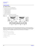
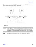
Cabling and Power Up Voltage Check (Additional Procedure) Voltage Check (Additional Procedure) The voltage check ensures that all phases (and neutral, for international systems) are connected correctly to the cabinet and that the AC input voltage is within limits. This procedure must be performed if the previous voltage check procedure did not yield the expected results as previously outlined. NOTE If a UPS is used, refer to applicable UPS documentation for information to connect the server and to check the UPS output voltage. UPS User Manual documentation is shipped with the UPS. Documentation can also be found at http://www.hp.com/racksolutions. Step 1. Verify that site power is OFF. Step 2. Open the site circuit breakers. Step 3. Verify that the receptacle ground connector is connected to ground. See Figure 4-5 for connector details. Step 4. Set the site power circuit breaker to ON. Figure 4-5 Wall Receptacle Pinouts WARNING There is a risk of shock hazard while testing primary power. Use properly insulated probes. Step 5. Verify that the voltage between receptacle pins x and y is between 200 and 240 V AC. Step 6. Set the site power circuit breaker to OFF. Step 7. Ensure that power is removed from the server. Step 8. Route and connect the server power connector to the site power receptacle. • For locking type receptacles, line up the key on the plug with the groove in the receptacle. • Push the plug into the receptacle and rotate to lock the connector in place. Chapter 4 63
-
 1
1 -
2
-
3
-
4
-
5
-
6
-
7
-
8
-
9
-
10
-
11
-
12
-
13
-
14
-
15
-
16
-
17
-
18
-
19
-
20
-
21
-
22
-
23
-
24
-
25
-
26
-
27
-
28
-
29
-
30
-
31
-
32
-
33
-
34
-
35
-
36
-
37
-
38
-
39
-
40
-
41
-
42
-
43
-
44
-
45
-
46
-
47
-
48
-
49
-
50
-
51
-
52
-
53
-
54
-
55
-
56
-
57
-
 58
58 -
 59
59 -
 60
60 -
 61
61 -
 62
62 -
 63
63 -
 64
64 -
 65
65 -
 66
66 -
 67
67 -
 68
68 -
69
-
70
-
71
-
72
-
73
-
74
-
75
-
76
-
77
-
78
-
79
-
80
 |
 |
