HP rp8440 User Service Guide, Sixth Edition - HP Integrity rx8640, HP 9000 rp8 - Page 175
Removing the BPS, Table 6-4 N+1 BPS-to-Cell Board Configuration
 |
View all HP rp8440 manuals
Add to My Manuals
Save this manual to your list of manuals |
Page 175 highlights
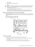
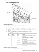
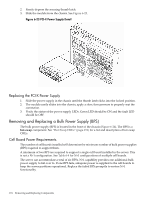
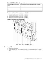
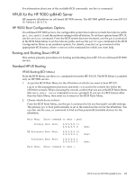
Table 6-4 N+1 BPS-to-Cell Board Configuration Number of Cell Boards Installed in the Server 1 2 3 4 Number of Operational BPS Installed to Maintain N+1 Functionality 3 4 5 6 The power distribution for the bulk power supplies follows: • A0 input provides power to BPS 0, BPS 1, and BPS 2 • A1 input provides power to BPS 3, BPS 4, and BPS 5 • B0 input provides power to BPS 0, BPS 1, and BPS 2 • B1 input provides power to BPS 3, BPS 4, and BPS 5 Figure 6-24 BPS Location (Front Bezel Removed) BPS 0 BPS 1 BPS 2 BPS 3 BPS 4 BPS 5 Removing the BPS 1. Remove the front bezel. 2. Isolate the failing BPS. Table 6-5 defines the states of the single multicolored LED on the BPS. Removing and Replacing a Bulk Power Supply (BPS) 175
-
 1
1 -
2
-
3
-
4
-
5
-
6
-
7
-
8
-
9
-
10
-
11
-
12
-
13
-
14
-
15
-
16
-
17
-
18
-
19
-
20
-
21
-
22
-
23
-
24
-
25
-
26
-
27
-
28
-
29
-
30
-
31
-
32
-
33
-
34
-
35
-
36
-
37
-
38
-
39
-
40
-
41
-
42
-
43
-
44
-
45
-
46
-
47
-
48
-
49
-
50
-
51
-
52
-
53
-
54
-
55
-
56
-
57
-
58
-
59
-
60
-
61
-
62
-
63
-
64
-
65
-
66
-
67
-
68
-
69
-
70
-
71
-
72
-
73
-
74
-
75
-
76
-
77
-
78
-
79
-
80
-
81
-
82
-
83
-
84
-
85
-
86
-
87
-
88
-
89
-
90
-
91
-
92
-
93
-
94
-
95
-
96
-
97
-
98
-
99
-
100
-
101
-
102
-
103
-
104
-
105
-
106
-
107
-
108
-
109
-
110
-
111
-
112
-
113
-
114
-
115
-
116
-
117
-
118
-
119
-
120
-
121
-
122
-
123
-
124
-
125
-
126
-
127
-
128
-
129
-
130
-
131
-
132
-
133
-
134
-
135
-
136
-
137
-
138
-
139
-
140
-
141
-
142
-
143
-
144
-
145
-
146
-
147
-
148
-
149
-
150
-
151
-
152
-
153
-
154
-
155
-
156
-
157
-
158
-
159
-
160
-
161
-
162
-
163
-
164
-
165
-
166
-
167
-
168
-
169
-
 170
170 -
 171
171 -
 172
172 -
 173
173 -
 174
174 -
 175
175 -
 176
176 -
 177
177 -
 178
178 -
 179
179 -
 180
180 -
181
-
182
-
183
-
184
-
185
-
186
-
187
-
188
-
189
-
190
-
191
-
192
-
193
-
194
-
195
-
196
-
197
 |
 |
Table 6-4 N+1 BPS-to-Cell Board Configuration
Number of Operational BPS Installed to Maintain N+1 Functionality
Number of Cell Boards Installed in the
Server
3
1
4
2
5
3
6
4
The power distribution for the bulk power supplies follows:
•
A0 input provides power to BPS 0, BPS 1, and BPS 2
•
A1 input provides power to BPS 3, BPS 4, and BPS 5
•
B0 input provides power to BPS 0, BPS 1, and BPS 2
•
B1 input provides power to BPS 3, BPS 4, and BPS 5
Figure 6-24 BPS Location (Front Bezel Removed)
BPS 0
BPS 1
BPS 2
BPS 3
BPS 4
BPS 5
Removing the BPS
1.
Remove the front bezel.
2.
Isolate the failing BPS.
Table 6-5
defines the states of the single multicolored LED on the
BPS.
Removing and Replacing a Bulk Power Supply (BPS)
175