HP rp8440 User Service Guide, Sixth Edition - HP Integrity rx8640, HP 9000 rp8 - Page 50
Lifting the Server Cabinet Manually, Using the RonI Model 17000 SP 400 Lifting Device
 |
View all HP rp8440 manuals
Add to My Manuals
Save this manual to your list of manuals |
Page 50 highlights
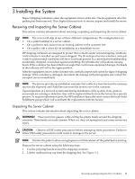
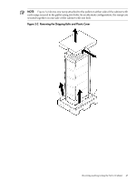
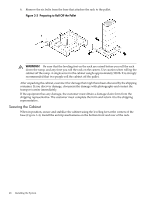
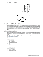
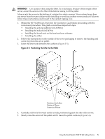
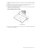
Data cables • CAT 5 cables • Fibre optic cables • SCSI cables • SCSI terminators Lifting the Server Cabinet Manually Use this procedure only if no HP approved lift is available. CAUTION: This procedure must only be performed by four qualified HP Service Personnel utilizing proper lifting techniques and procedures. 1. Follow the instructions on the outside of the service packaging to remove the banding and cardboard top from the server pallet. 2. Reduce the weight by removing all bulk power supplies and cell boards. Place each on an ESD approved surface. CAUTION: System damage can occur through improper removal and reinstallation of bulk power supplies and cell boards. See Chapter 6, "Removal and Replacement" for the correct procedures to remove and reinstall these components. 3. Locate the four positioning handles on the sides of the system. They are colored blue and located close to each base corner of the unit. 4. Ensure that the tabs of the vertical support brackets are in the down position so they rest on the slide rails when the server is lowered over the slides. There are two brackets on each side of the server chassis. 5. Unfold the handles so that they are extended out from the unit. The server is now ready for manual lifting by the four qualified HP Service Personnel. 6. Lift the server into place and secure as required. 7. After the server is secured, reinstall the previously removed cell boards and bulk power supplies. Using the RonI Model 17000 SP 400 Lifting Device Use the lifter designed by the RonI company to rack-mount the server. The lifter can raise 400 lb/182 kg to a height of 5 feet. The lifter can be broken down into several components. When completely broken down, no single component weighs more than 25 lb/12 kg. The ability to break the lifter down makes it easy to transport from the office to the car and then to the customer site. Documentation for the RonI lifter has been written by RonI and is available on their website: http://www.liftoflex.com/lift-o-flex.html. Complete details on how to assemble the lifter, troubleshoot the lifter, and maintain the lifter are provided by RonI. Use the following procedure to unload the server from the pallet after the lifter is assembled. 50 Installing the System
-
 1
1 -
2
-
3
-
4
-
5
-
6
-
7
-
8
-
9
-
10
-
11
-
12
-
13
-
14
-
15
-
16
-
17
-
18
-
19
-
20
-
21
-
22
-
23
-
24
-
25
-
26
-
27
-
28
-
29
-
30
-
31
-
32
-
33
-
34
-
35
-
36
-
37
-
38
-
39
-
40
-
41
-
42
-
43
-
44
-
 45
45 -
 46
46 -
 47
47 -
 48
48 -
 49
49 -
 50
50 -
 51
51 -
 52
52 -
 53
53 -
 54
54 -
 55
55 -
56
-
57
-
58
-
59
-
60
-
61
-
62
-
63
-
64
-
65
-
66
-
67
-
68
-
69
-
70
-
71
-
72
-
73
-
74
-
75
-
76
-
77
-
78
-
79
-
80
-
81
-
82
-
83
-
84
-
85
-
86
-
87
-
88
-
89
-
90
-
91
-
92
-
93
-
94
-
95
-
96
-
97
-
98
-
99
-
100
-
101
-
102
-
103
-
104
-
105
-
106
-
107
-
108
-
109
-
110
-
111
-
112
-
113
-
114
-
115
-
116
-
117
-
118
-
119
-
120
-
121
-
122
-
123
-
124
-
125
-
126
-
127
-
128
-
129
-
130
-
131
-
132
-
133
-
134
-
135
-
136
-
137
-
138
-
139
-
140
-
141
-
142
-
143
-
144
-
145
-
146
-
147
-
148
-
149
-
150
-
151
-
152
-
153
-
154
-
155
-
156
-
157
-
158
-
159
-
160
-
161
-
162
-
163
-
164
-
165
-
166
-
167
-
168
-
169
-
170
-
171
-
172
-
173
-
174
-
175
-
176
-
177
-
178
-
179
-
180
-
181
-
182
-
183
-
184
-
185
-
186
-
187
-
188
-
189
-
190
-
191
-
192
-
193
-
194
-
195
-
196
-
197
 |
 |