HP rp8440 User Service Guide, Sixth Edition - HP Integrity rx8640, HP 9000 rp8 - Page 21
Front Panel, Front Panel Indicators and Controls, Enclosure Status LEDs, Cell Board
 |
View all HP rp8440 manuals
Add to My Manuals
Save this manual to your list of manuals |
Page 21 highlights
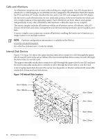
The PCI card bulkhead connectors are located at the rear top. The PCI X OLR fan modules are located in front of the PCI cards. They are housed in plastic carriers. The 12 rear OLR fans attached outside the chassis house 120-mm exhaust fans. The cell boards are located on the right side of the server behind a removable side cover. For rack mounted servers on slides, the rack front door requires removal if it is hinged on the right side of the rack. Removal will allow unrestricted access to server sides after sliding server out for service.. The two redundant core I/O cards are positioned vertically end-to-end at the rear of the chassis. Redundant line cords attach to the AC power receptacles at the bottom rear. Two 20-amp cords are required to power the server. Two additional line cords provide redundancy. Access the system backplane by removing the left side cover. The system backplane hinges from the lower edge and is anchored at the top with a single large jack screw assembly. The SCSI ribbon cable assembly also routes across and fastens to the backside of the system backplane near the connectors that attach the core I/O boards. The blue deployment handles hinge outward for manual lift. When server is slide mounted, they retract against chassis to enable slide action without obstruction. Front Panel Front Panel Indicators and Controls The front panel, located on the front of the server, includes the power switch. See Figure 1-5. Enclosure Status LEDs The following status LEDs are on the front panel: • Locate LED (blue) • Power LED (tricolor) • Management processor (MP) status LED (tricolor) • Cell 0, 1, 2, 3 status (tricolor) LEDs Figure 1-5 Front Panel LEDs and Power Switch Cell Board The cell board, illustrated in Figure 1-6, contains the processors, main memory, and the CC application specific integrated circuit (ASIC) which interfaces the processors and memory with the I/O. The CC is the heart of the cell board, providing a crossbar connection that enables communication with other cell boards in the system. It connects to the processor dependent hardware (PDH) and microcontroller hardware. Each cell board holds up to four processor modules and 16 memory DIMMs. One to four cell boards can be installed in the server. A cell board can be selectively powered off for adding processors, memory or maintenance of the cell board, without affecting cells in other configured partitions. Detailed Server Description 21
-
 1
1 -
2
-
3
-
4
-
5
-
6
-
7
-
8
-
9
-
10
-
11
-
12
-
13
-
14
-
15
-
 16
16 -
 17
17 -
 18
18 -
 19
19 -
 20
20 -
 21
21 -
 22
22 -
 23
23 -
 24
24 -
 25
25 -
 26
26 -
27
-
28
-
29
-
30
-
31
-
32
-
33
-
34
-
35
-
36
-
37
-
38
-
39
-
40
-
41
-
42
-
43
-
44
-
45
-
46
-
47
-
48
-
49
-
50
-
51
-
52
-
53
-
54
-
55
-
56
-
57
-
58
-
59
-
60
-
61
-
62
-
63
-
64
-
65
-
66
-
67
-
68
-
69
-
70
-
71
-
72
-
73
-
74
-
75
-
76
-
77
-
78
-
79
-
80
-
81
-
82
-
83
-
84
-
85
-
86
-
87
-
88
-
89
-
90
-
91
-
92
-
93
-
94
-
95
-
96
-
97
-
98
-
99
-
100
-
101
-
102
-
103
-
104
-
105
-
106
-
107
-
108
-
109
-
110
-
111
-
112
-
113
-
114
-
115
-
116
-
117
-
118
-
119
-
120
-
121
-
122
-
123
-
124
-
125
-
126
-
127
-
128
-
129
-
130
-
131
-
132
-
133
-
134
-
135
-
136
-
137
-
138
-
139
-
140
-
141
-
142
-
143
-
144
-
145
-
146
-
147
-
148
-
149
-
150
-
151
-
152
-
153
-
154
-
155
-
156
-
157
-
158
-
159
-
160
-
161
-
162
-
163
-
164
-
165
-
166
-
167
-
168
-
169
-
170
-
171
-
172
-
173
-
174
-
175
-
176
-
177
-
178
-
179
-
180
-
181
-
182
-
183
-
184
-
185
-
186
-
187
-
188
-
189
-
190
-
191
-
192
-
193
-
194
-
195
-
196
-
197
 |
 |
