HP t5335z Troubleshooting Guide: HP t5335 Thin Clients - Page 10
Diagnostics and Troubleshooting, LEDs - boot
 |
View all HP t5335z manuals
Add to My Manuals
Save this manual to your list of manuals |
Page 10 highlights
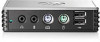
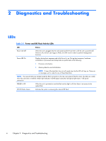
2 Diagnostics and Troubleshooting LEDs Table 2-1 Power and IDE Flash Activity LEDs LED Status Power LED Off When the unit is plugged into the wall socket and the Power LED is off, the unit is powered off. However, the network can trigger a Wake On LAN event in order to perform management functions. Power LED On Displays during boot sequence and while the unit is on. During boot sequence, hardware initialization is processed and startup tests are performed on the following: ● Processor initialization ● Memory detection and initialization NOTE: If one of the tests fails, the unit will simply stop, but the LED will stay on. There are no messages sent to video for any of these failed tests. NOTE: The network LEDs are located inside the RJ-45 connector on the top, rear panel of the thin client. The LEDs are visible when the connector is installed. Amber light indicates 100-MB speed connection and green lght means 1-GB speed connection. IDE LED is Off When the unit is powered on and the flash activity light is off, then there is no access to the system flash. IDE LED blinks Green Indicates the system is accessing the internal IDE flash. 4 Chapter 2 Diagnostics and Troubleshooting
-
 1
1 -
2
-
3
-
4
-
 5
5 -
 6
6 -
 7
7 -
 8
8 -
 9
9 -
 10
10 -
 11
11 -
 12
12 -
 13
13 -
 14
14 -
 15
15 -
16
-
17
-
18
-
19
-
20
-
21
-
22
-
23
-
24
-
25
-
26
-
27
-
28
-
29
-
30
-
31
-
32
 |
 |
