Hitachi 43FDX01B Service Manual - Page 19
EN 19, LGE PDP 2K6
 |
View all Hitachi 43FDX01B manuals
Add to My Manuals
Save this manual to your list of manuals |
Page 19 highlights
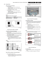
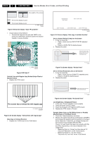
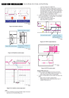
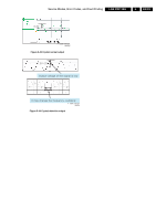
Service Modes, Error Codes, and Fault Finding LGE PDP 2K6 5. EN 19 5.2.2 Display Defects Half of the Screen is Not Shown • On the XR board: 1. Check if the power connector of the XR board is plugged in correctly. 2. Check if the 60-pin connection of the CTRL board to the XR board is plugged in correctly. • On the XL board: 1. Check if the power connector of the XL board is plugged in correctly. 2. Check if the 60-pin connection of the CTRL board to the XL board is plugged in correctly. • Replace relevant X board. Notes: Relationship between Screen and X board: Screen Left half of the screen Right half of the screen X-board Right X-board Left X-board Left half of the screen Right half of the screen Image No image G_16390_044.eps 110806 Figure 5-24 Screen display "1/2 display" Vertical Parts of the Screen are Missing 1. This can be related to a problem between the Data TCP and the X board. 2. Verify that the connector of the Data TCP is well connected to the X board (it corresponds to the part of the screen that does not display the image). 3. Confirm whether the Data TCP fails (examination with the naked eye of blown ICs or other parts included). - If an IC is damaged: replace the panel. - In case of an X board short circuit or an open PWB pattern: when the TCP IC is not defective, replace the X board. Notes: • Example of screen display (any of the Data TCPs can be shown). - Examine with the naked eye traces of blown ICs [3] or other parts. G_16390_081.eps 010906 Figure 5-26 Data TCP IC examination Unusual Pattern on Display 1. In case of generation of an unusual pattern of the Data TCP IC unit as shown in the picture below, check the fixation of the relevant X board. If that doesn't help, replace the X board. 2. In case of "Case 1": - Check the connection between the Data TCP connector and the IC. - Replace the relevant X board, or the Control board. 3. In case of "Case 2" or "Case 3": - Check the connection between the CTRL board and the relevant X board. - Replace the relevant X board or the CTRL board. Note: • If the silicon tape between the X board and the heatsink feels (partially) hard, it has to be replaced. Case 1 Case 2 Case 3 All Partial Not at all F_15590_009.eps 040705 Figure 5-25 Screen display "Vertical parts missing" • How to examine the Data TCP IC - Connect [1] "Va Power" to the minus and [2] "GND" to the plus of an ohmmeter, and then examine the diode in forward or reverse direction. G_16390_045.eps 140806 Figure 5-27 Possible cases Scan FPC Problem 1. Check the connection between Y DRV board and Scan FPC. 2. If the Scan IC is defective, replace the Y DRV board.
-
 1
1 -
2
-
3
-
4
-
5
-
6
-
7
-
8
-
9
-
10
-
11
-
12
-
13
-
 14
14 -
 15
15 -
 16
16 -
 17
17 -
 18
18 -
 19
19 -
 20
20 -
 21
21 -
 22
22 -
 23
23 -
 24
24 -
25
-
26
-
27
-
28
-
29
-
30
-
31
-
32
-
33
-
34
 |
 |
