Hitachi 43FDX01B Service Manual - Page 27
EN 27, LGE PDP 2K6
 |
View all Hitachi 43FDX01B manuals
Add to My Manuals
Save this manual to your list of manuals |
Page 27 highlights
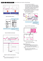
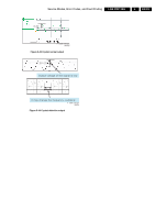
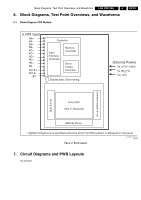
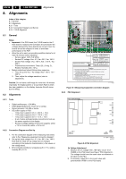
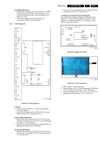
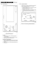
Va Voltage Adjustment 1. Measure the Va voltage (55...65 VDC) on pin 1 of CN806 on the PSU board (see Figure "PSU Alignment"). The voltage should have the same value as indicated on the label on the PSU. 2. If necessary, adjust Va to its correct value with potentiometer VR351 on the PSU board. 8.2.4 Y-SUS Alignment P1 Wave form P2 P2 P3 P4 P1 FS1 FS2 FS3 Alignments LGE PDP 2K6 8. EN 27 2. Adjust -Vy to the value indicated on the voltage sticker with potentiometer VRy on the Y-SUS board. Y -SUS Set-up Voltage Waveform Adjustment Now connect the oscilloscope between the Waveform test point on the Y-Driver board and GND (see Figure ""Y-SUS Alignment"). Trigger with Vs-DA on the Control board (see Figure "Trigger point Vs-DA"). CTRL board P2 IC12 +3.3V P7 1 X1 P3 D12 D13 D14 D15 +1.8V IC1 VS_DA IC11 +3.3V IC13 TRIGGER POINT P4 P10 P11 Figure 8-4 Trigger point Vs-DA P1 G_16391_012.eps 020707 P5 Setup VR3 Setdn VR2 P4 P6 Vsc -Vy Vsc VRsc VRy P8 C51 -Vy R36 P152 P7 P8 G_16391_011.eps 020707 Figure 8-3 Y-SUS alignment Condition • Set up a situation as shown in "Measuring equipment connection diagram". • Check if the voltages Vs and Va of the PSU are correct (see PSU label and PSU Alignment 8.2.3). Vscan Voltage Adjustment 1. Measure the Vscan voltage across C51 (or on the "Vsc" test point on the right of connector P4) on the Y-SUS board (see Figure "Y-SUS Alignment"). 2. Adjust Vsc to the value indicated on the voltage sticker with potentiometer VRsc on the Y-SUS board. -Vy Voltage Adjustment 1. Measure the Vy voltage across R36 (or on the "Vy" test point on the DC converter) on the Y-SUS board (see Figure "Y-SUS Alignment"). G_16391_008.eps 020707 Figure 8-5 V set-up waveform 1. Refer to Figure "V set-up waveform". 2. Adjust Vsetup to 150 ± 1 V with potentiometer VR3/Setup on the Y-SUS board (see Figure "Y-SUS Alignment"). 3. Adjust the duration of time-interval "A" to 10 ± 5 µsec with potentiometer VR2/Setdown on the Y-SUS board.
-
 1
1 -
2
-
3
-
4
-
5
-
6
-
7
-
8
-
9
-
10
-
11
-
12
-
13
-
14
-
15
-
16
-
17
-
18
-
19
-
20
-
21
-
 22
22 -
 23
23 -
 24
24 -
 25
25 -
 26
26 -
 27
27 -
 28
28 -
 29
29 -
 30
30 -
 31
31 -
 32
32 -
33
-
34
 |
 |
