Hitachi 43FDX01B Service Manual - Page 26
EN 26, LGE PDP 2K6
 |
View all Hitachi 43FDX01B manuals
Add to My Manuals
Save this manual to your list of manuals |
Page 26 highlights
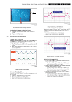
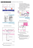
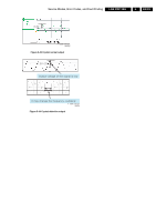
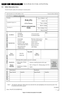
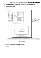
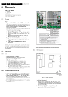
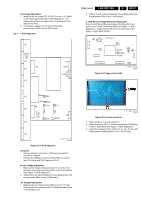
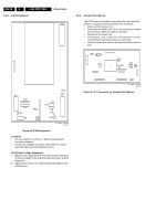
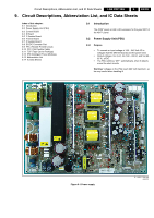
EN 26 8. LGE PDP 2K6 8. Alignments Alignments Index of this chapter: 8.1 General 8.2 Alignments 8.2.1 Tools 8.2.2 Connection Diagram and Set-Up 8.2.4 Y-SUS Alignment 8.1 General Notes: • Important: if the PSU board, the Y-SUS board or the Z- SUS board is replaced, the technician should check if the voltages delivered by these boards are correct. If not, the boards should be realigned in order to avoid bad performance of the PDP. • Allow the set to warm up according conditions below for at least 10 minutes before adjusting. - Service signal: 100% Full White. - Service DC voltage: Vcc= 5 V, Va= 60 V, Vs= 180 V. - DC/DC Pack voltage: Vsc= 120 V, Vzb = 100 V, -Vy= - 200 V - Preliminaries environment: Temp (25 ± 5 deg. C), Relative Humidity (65 ± 10%). • Module adjustment should follow below sequence. 1. First, set up the Vsc / -Vy voltage (Vsc= 120 V, -Vy= 200 V). 2. Then, adjust the voltage waveform (refer to adjustment). Caution: Do not leave a still image for more than 10 minutes (especially The Digital pattern or Cross Hatch Pattern which has clear gradation) on the display, because this will cause burn-in effects. 8.2 Alignments 8.2.1 Tools • Digital oscilloscope: > 200 MHz. • DVM (Digital Multimeter): Fluke 187 or similar. • Signal generator: VG-828 or similar. • DC power supply or PSU: - 1 DC power supply for Vs: 0 - 200 V, > 10 A. - 1 DC power supply for Va: 0 - 100 V, > 5 A. - 1 DC power supply for 5V: 0 - 10 V, > 10 A. - A set of wires and appropriate connectors to hook up the power supplies to the display. - Required voltage stability of the power supplies: within ± 1% for Vs and Va, within ± 3% for 5V. 8.2.2 Connection Diagram and Set-Up 1. For the connection diagram of the measuring instrument, refer to Fig. "Measuring equipment connection diagram". 2. Set-up the initial voltage Vcc= 5 V, Va= 60 V, Vs= 180 V. Note that the initial set-up voltage can be changed according to the module's characteristics (= the values on the voltage label). 3. Environmental conditions: temperature 25 ± 5 °C, relative humidity 65 ± 10 %. Waveform testpoint VR3 VR2 Signal Generator (VG-825) Power ++- 5V 1.2 A External DC Power Supply for 5V 65V 0.01A External DC Power Supply for Va 180V 1.3A External + - DC Power Supply for Vs Caution (1) The power of the signal generator should be turned "ON" before turning "ON" the power of the DC power supply. (2) The voltage of DC power supplies, in standard of Module input voltage, should be preset as follows: Vcc: 5V, Va: 60V, Vs: 180V (3) The power of power supply must turned "ON" by the following sequence. Reverse direction when turning "off". * Module "ON" : 5V => Va => Vs, Module "OFF": Vs => Va => 5V (4) Signal generator should be selected with 1024 x 768 (XGA) mode. Also the use of the normal PSU (Power Supply Unit) is possible G_16390_023.eps 170806 Figure 8-1 Measuring equipment connection diagram 8.2.3 PSU Alignment PSU (3501Q00203B) Vs adj VR551 Va adj VR351 G_16391_008.eps 020707 CN806 CN807 1M02 CN805 1M10 Z001 F001 1M03 1M46 G_16391_009.eps 020707 Figure 8-2 PSU Alignment Vs Voltage Adjustment 1. Measure the Vs voltage (180...195 VDC) on pin 10 of CN806 on the PSU board (see Figure "PSU Alignment"). The voltage should have the same value as indicated on the label on the PSU. 2. If necessary, adjust Vs to its correct value with potentiometer VR551 on the PSU board.
-
 1
1 -
2
-
3
-
4
-
5
-
6
-
7
-
8
-
9
-
10
-
11
-
12
-
13
-
14
-
15
-
16
-
17
-
18
-
19
-
20
-
 21
21 -
 22
22 -
 23
23 -
 24
24 -
 25
25 -
 26
26 -
 27
27 -
 28
28 -
 29
29 -
 30
30 -
 31
31 -
32
-
33
-
34
 |
 |
