Hitachi 43FDX01B Service Manual - Page 25
Block Diagrams, Test Point Overviews, and Waveforms, Circuit Diagrams and PWB Layouts
 |
View all Hitachi 43FDX01B manuals
Add to My Manuals
Save this manual to your list of manuals |
Page 25 highlights
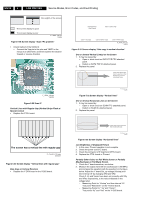
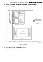
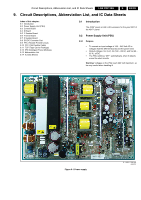
Block Diagrams, Test Point Overviews, and Waveforms LGE PDP 2K6 6. 6. Block Diagrams, Test Point Overviews, and Waveforms EN 25 6.1 Block Diagram PDP Module (LVDS input) RA+ RARB+ RBRC+ RCRD+ RDRE+ RE- RCLK+ RCLK- I2C Controller Input Interface Controller Memory Controller Driver Timing Controller Display data, Driver timing (External Power) Vs (175V~190V) Va (60+ 1V) Vcc (5V) Scan Driver Common sustain driver Color PDP 1024 X 768 pixels Address Driver ත Applied Voltage level is specified at the time when Full-White pattern is displayed on the panel. G_16390_079.eps 310806 Figure 6-1 Block Diagram 7. Circuit Diagrams and PWB Layouts Not applicable
-
 1
1 -
2
-
3
-
4
-
5
-
6
-
7
-
8
-
9
-
10
-
11
-
12
-
13
-
14
-
15
-
16
-
17
-
18
-
19
-
 20
20 -
 21
21 -
 22
22 -
 23
23 -
 24
24 -
 25
25 -
 26
26 -
 27
27 -
 28
28 -
 29
29 -
 30
30 -
31
-
32
-
33
-
34
 |
 |

Block Diagrams, Test Point Overviews, and Waveforms
EN 25
LGE PDP 2K6
6.
6.
Block Diagrams, Test Point Overviews, and Waveforms
6.1
Block Diagram PDP Module
Figure 6-1 Block Diagram
7.
Circuit Diagrams and PWB Layouts
Not applicable
Applied Volt
a
ge level i
s
s
pecified
a
t the time when F
u
ll-White p
a
ttern i
s
di
s
pl
a
yed on the p
a
nel.
Color PDP
1024 X 76
8
pixel
s
Addre
ss
Driver
r
e
v
i
r
D
n
a
c
S
r
e
v
i
r
d
n
i
a
t
s
u
s
n
o
m
m
o
C
Vcc (5V)
Di
s
pl
a
y d
a
t
a
, Driver timing
Memory
Controller
Driver
Timing
Controller
Inp
u
t
Interf
a
ce
Controller
V
a
(60+1V)
V
s
(175V~190V)
Controller
(Extern
a
l Power)
RA+
RA-
RB+
RD+
RD-
RB-
RC+
RC-
RE+
RE-
RCLK-
RCLK+
(LVD
S
inp
u
t)
I2C
G_16
3
90_079.ep
s
3
10
8
06