Hitachi 43FDX01B Service Manual - Page 7
Mechanical Instructions - power supply
 |
View all Hitachi 43FDX01B manuals
Add to My Manuals
Save this manual to your list of manuals |
Page 7 highlights
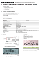
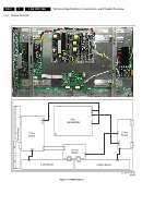
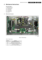
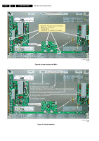
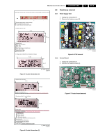
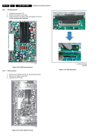
Mechanical Instructions 4. Mechanical Instructions Index of this chapter: 4.1 Mechanical Overviews 4.2 Panel/assy removal 4.2.1 Power Supply Unit 4.2.2 Control Board 4.2.3 Y Sustain Board 4.2.4 Y Driver Board 4.2.5 Z-Sustain board 4.2.6 X-board 4.1 Mechanical Overviews LGE PDP 2K6 4. EN 7 8 7 6 1 4 2 3 Figure 4-1 Cable dressing Table 4-1 Cable function Cable No. 1 2 & 3 4 & 5 6 7 & 8 Function Drive signal for Y waveform RGB data to be transferred to panel 5V and Va supply for X-boards Left and Right Drive signal for Z-waveform Va, Vs and 5 V supply for PDP operation 5 G_16391_004.eps 020707
-
 1
1 -
 2
2 -
 3
3 -
 4
4 -
 5
5 -
 6
6 -
 7
7 -
 8
8 -
 9
9 -
 10
10 -
 11
11 -
 12
12 -
13
-
14
-
15
-
16
-
17
-
18
-
19
-
20
-
21
-
22
-
23
-
24
-
25
-
26
-
27
-
28
-
29
-
30
-
31
-
32
-
33
-
34
 |
 |

Mechanical Instructions
EN 7
LGE PDP 2K6
4.
4.
Mechanical Instructions
Index of this chapter:
4.1
Mechanical Overviews
4.2
Panel/assy removal
4.2.1
Power Supply Unit
4.2.2
Control Board
4.2.3
Y Sustain Board
4.2.4
Y Driver Board
4.2.5
Z-Sustain board
4.2.6
X-board
4.1
Mechanical Overviews
Figure 4-1 Cable dressing
Table 4-1 Cable function
G_16391_004.eps
020707
8
4
1
2
3
6
5
7
Cable No.
Function
1
Drive signal for Y waveform
2 & 3
RGB data to be transferred to panel
4 & 5
5V and Va supply for X-boards Left and Right
6
Drive signal for Z-waveform
7 & 8
Va, Vs and 5 V supply for PDP operation