Honeywell NS2 Configuration Guide - Page 1

Honeywell NS2 Manual

Page 1 highlights

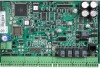
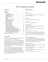
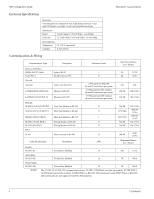
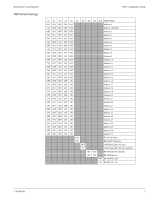
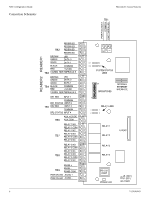
NS2 Configuration Guide Contents Description 1 Specifications 1 Power 1 Backup Battery 1 Secondary Backup Battery 1 Reader & Aux Power 1 Reader Wiring 2 Supervised Input Wiring 2 Inputs 2 Outputs 3 Enclosure Specifications 4 Communications & Wiring 4 DIP Switch Settings 5 Connection Schematic 6 Configuration Diagrams 7 RS-232 Connection 7 RS-485 Connection 8 NSLAN1 Connection 9 LANSRL100 Connection 10 LANSRLU1 Connection 11 Lease Line Modem Connection 12 RS-485 Short Haul Modem Connection 13 RS-232 Short Haul Modem Connection 14 M-9600 Dial-up Modem, RS-485 Connection 15 M-56K Dial-up Modem, RS-485 Connection 16 Fiber Converter to RS-485 Connection 17 485-PCI/NS2 Panel Connection Detail 18 Frequently Asked Questions 19 Description The NS2 is a two reader panel providing access control for up to two doors through the use of Wiegand readers. The NS2 may be used as a standalone panel with independent card and transaction storage or, with a software upgrade, as a fully monitored online access control device. Communication to the front-end computer is achieved through an RS-232 serial cable (included with installation kit) or an optional RS-485 interface. Each RS-485 interface is capable of communicating with up to 31 panels. The NS2 is designed for tile mount using the ENC10 enclosure. The I/O terminals are organized by operational utility with connectors for power and RS-485 communications located on the lower right followed from right to left by the relays, auxiliary power, door control inputs, and readers. The Tamper and External Power Fail terminal are located at the left edge above the main line of connectors. Specifications Power AC Non-Polarized: 16.5 VAC utilizing a UL-listed 50 VA Class 2 transformer (TB9-4 AC+/TB9-5 AC-) or DC Polarized: 24 VDC, 1.25 Amp (TB9-4 DC+/TB9-5 DC-) Power Wire Two-wire, 18 AWG, shielded cable. Backup Battery Casil 12 VDC (NCI Part #: BAT-3) 4Ah, sealed acid/lead backup battery (J6 DC+/J7 DC-) Backup battery will provide 2.5 hours of standby backup power. Charging voltage: 13.7 +/- 0.1 VDC NOTE: The NS2 panel has deep discharge protection built in for the protection of the battery and will only utilize a backup battery down to 10.2 VDC before the NS2 shuts down. Backup battery should be replaced 2 to 2.5 years: more often if panel has a high rate of backup use. Secondary Backup Battery The NS2 panel memory is backed up using a super capacitor for one week in the absence of power or a backup battery. The super capacitor will backup panel memory and real-time clock and does not require maintenance or replacement. Reader & Aux Power Reader and AUX power is supplied at 10.8-12.7 VDC with a maximum current of 600 mA. Five volt (5 VDC) readers require five-volt regulators (Northern part no. 5VRDREG) Maximum draw is less then 600 mA: (Reader 1+ Reader 2 + Aux Power) < 600 mA. NOTE: Aux power must not be used to power locks. 7-101004-01 1

  • 1
  • 2
  • 3
  • 4
  • 5
  • 6
  • 7
  • 8
  • 9
  • 10
  • 11
  • 12
  • 13
  • 14
  • 15
  • 16
  • 17
  • 18
  • 19
  • 20

7-101004-01
1
NS2 Configuration Guide
Contents
Description . . . . . . . . . . . . . . . . . . . . . . . . . . . . . . . . . . . . . . . 1
Specifications . . . . . . . . . . . . . . . . . . . . . . . . . . . . . . . . . . . . . 1
Power . . . . . . . . . . . . . . . . . . . . . . . . . . . . . . . . . . . . . . . . 1
Backup Battery. . . . . . . . . . . . . . . . . . . . . . . . . . . . . . . . . 1
Secondary Backup Battery. . . . . . . . . . . . . . . . . . . . . . . . 1
Reader & Aux Power . . . . . . . . . . . . . . . . . . . . . . . . . . . . 1
Reader Wiring . . . . . . . . . . . . . . . . . . . . . . . . . . . . . . . . . 2
Supervised Input Wiring . . . . . . . . . . . . . . . . . . . . . . . . . 2
Inputs . . . . . . . . . . . . . . . . . . . . . . . . . . . . . . . . . . . . . . . . 2
Outputs . . . . . . . . . . . . . . . . . . . . . . . . . . . . . . . . . . . . . . . 3
Enclosure Specifications . . . . . . . . . . . . . . . . . . . . . . . . . 4
Communications & Wiring . . . . . . . . . . . . . . . . . . . . . . . 4
DIP Switch Settings . . . . . . . . . . . . . . . . . . . . . . . . . . . . . 5
Connection Schematic . . . . . . . . . . . . . . . . . . . . . . . . . . . 6
Configuration Diagrams . . . . . . . . . . . . . . . . . . . . . . . . . . . . . 7
RS-232 Connection . . . . . . . . . . . . . . . . . . . . . . . . . . . . . 7
RS-485 Connection . . . . . . . . . . . . . . . . . . . . . . . . . . . . . 8
NSLAN1 Connection. . . . . . . . . . . . . . . . . . . . . . . . . . . . 9
LANSRL100 Connection. . . . . . . . . . . . . . . . . . . . . . . . 10
LANSRLU1 Connection . . . . . . . . . . . . . . . . . . . . . . . . 11
Lease Line Modem Connection . . . . . . . . . . . . . . . . . . . 12
RS-485 Short Haul Modem Connection . . . . . . . . . . . . 13
RS-232 Short Haul Modem Connection . . . . . . . . . . . . 14
M-9600 Dial-up Modem, RS-485 Connection . . . . . . . 15
M-56K Dial-up Modem, RS-485 Connection . . . . . . . . 16
Fiber Converter to RS-485 Connection . . . . . . . . . . . . . 17
485-PCI/NS2 Panel Connection Detail . . . . . . . . . . . . . 18
Frequently Asked Questions
. . . . . . . . . . . . . . . . . . . . . . . . . . . . 19
Description
The NS2 is a two reader panel providing access control for up
to two doors through the use of Wiegand readers.
The NS2 may be used as a standalone panel with independent
card and transaction storage or, with a software upgrade, as a
fully monitored online access control device. Communication
to the front-end computer is achieved through an RS-232 serial
cable (included with installation kit) or an optional RS-485
interface. Each RS-485 interface is capable of communicating
with up to 31 panels.
The NS2 is designed for tile mount using the ENC10 enclo-
sure. The I/O terminals are organized by operational utility
with connectors for power and RS-485 communications
located on the lower right followed from right to left by the
relays, auxiliary power, door control inputs, and readers. The
Tamper and External Power Fail terminal are located at the left
edge above the main line of connectors.
Specifications
Power
AC Non-Polarized:
16.5 VAC utilizing a UL-listed 50 VA Class 2 transformer
(TB9-4 AC+/TB9-5 AC–)
or
DC Polarized:
24 VDC, 1.25 Amp (TB9-4 DC+/TB9-5 DC–)
Power Wire
Two-wire, 18 AWG, shielded cable.
Backup Battery
Casil 12 VDC (NCI Part #: BAT-3) 4Ah, sealed acid/lead
backup battery (J6 DC+/J7 DC–)
Backup battery will provide 2.5 hours of standby backup
power.
Charging voltage: 13.7 +/– 0.1 VDC
NOTE:
The NS2 panel has deep discharge protection built in for the
protection of the battery and will only utilize a backup battery down to
10.2 VDC before the NS2 shuts down. Backup battery should be
replaced 2 to 2.5 years: more often if panel has a high rate of backup
use.
Secondary Backup Battery
The NS2 panel memory is backed up using a super capacitor
for one week in the absence of power or a backup battery. The
super capacitor will backup panel memory and real-time clock
and does not require maintenance or replacement.
Reader & Aux Power
Reader and AUX power is supplied at 10.8-12.7 VDC with a
maximum current of 600 mA.
Five volt (5 VDC) readers require five-volt regulators (North-
ern part no. 5VRDREG)
Maximum draw is less then 600 mA: (Reader 1+ Reader 2 +
Aux Power) < 600 mA.
NOTE:
Aux power must not be used to power locks.