Honeywell NS2 Configuration Guide - Page 3
Outputs - access control
 |
View all Honeywell NS2 manuals
Add to My Manuals
Save this manual to your list of manuals |
Page 3 highlights
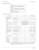
Honeywell Access Systems NS2 Configuration Guide Outputs Four form-C relays SPDT (Single Poll Double Throw) goldcontact relays are provided for controlling door locks or other output devices (I.E. sounder, burg panel, phone dialer....etc.). Output Terminal TB7-1 TB7-2 TB7-3 TB7-4 TB7-5 TB7-6 TB8-1 TB8-2 TB8-3 TB8-4 TB8-5 TB8-6 Description Normally Open (NO) Common (COM) Normally Closed (NC) Normally Open (NO) Common (COM) Normally Closed (NC) Normally Open (NO) Common (COM) Normally Closed (NC) Normally Open (NO) Common (COM) Normally Closed (NC) Relay/Output Number Relay 1 (Door 1) Relay 1 (Door 1) Relay 1 (Door 1) Relay 2 (Door 2) Relay 2 (Door 2) Relay 2 (Door 2) Relay 3 Relay 3 Relay 3 Relay 4 Relay 4 Relay 4 The energized or ON time for each relay can be configured by using either time zone control, or programmable pulse time via the host software. Relay 1 is defaulted to control the Door 1 lock & Relay 2 is defaulted for the Door 2 lock. Relay 3 & 4 are used as auxiliary relays for signaling other devices. All 4 relays are rated at 12 Amps / 28VDC for resistive loads and 6 Amps / 28VDC for inductive loads (data switching). NOTE: Once the relay pole has been used for an inductive load (including door strikes and magnetic locks) it should not be used for low current dry circuit applications. NOTE: Switching of inductive loads can cause EMI (Electromagnetic Interference) which may interfere with the normal operation of other equipment. To minimize premature contact failure and increase system reliability, contact circuit protection such as the S-4 suppressor is required. Locate this device as close as possible to the Door Strike / Maglock. 7-101004-01 3
-
 1
1 -
 2
2 -
 3
3 -
 4
4 -
 5
5 -
 6
6 -
 7
7 -
 8
8 -
 9
9 -
10
-
11
-
12
-
13
-
14
-
15
-
16
-
17
-
18
-
19
-
20
 |
 |
