Honeywell NS2 Configuration Guide - Page 11
LANSRLU1 Connection
 |
View all Honeywell NS2 manuals
Add to My Manuals
Save this manual to your list of manuals |
Page 11 highlights
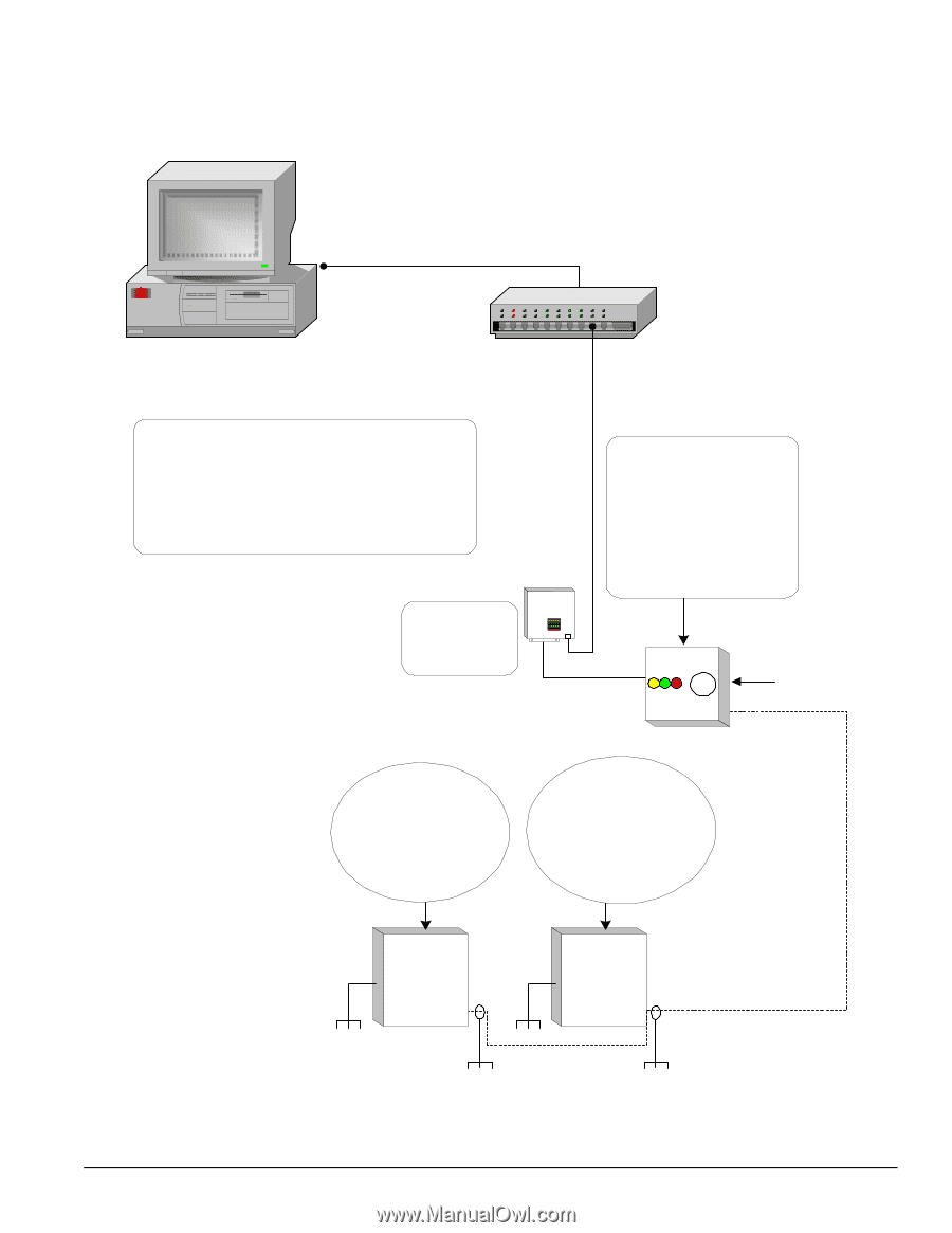
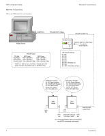
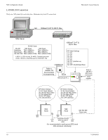
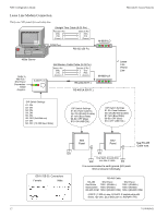
Honeywell Access Systems LANSRLU1 Connection Thirty-one panels for each drop line, Maximum sixty-four IP connections. NS2 Configuration Guide NIC 100BaseT (CAT 5) 328 Ft. Max. NStar Server HUB 100BaseT (CAT 5) 328 Ft. Max. RS-485 Cable RS-485 NS2 Panel NS2 Panel Red/White TB9-1 (RS485+) TB9-1 (RS485+) Black/Green TB9-2 (RS485-) TB9-2 (RS485-) RS-485 COM TB9-3 (RS485 COM) TB9-3 (RS485 COM) 4,000 ft. (1,200 m) max, 24 AWG, 2 twisted pairs with shield, 120 ohm, 23 pf (NCI part no. NCP2441-TN) LANSRLU1 DIP Switch Settings S1: ON S2: ON S3: ON S4: ON S5: ON S6: OFF (Ack/Nak on) S7: ON S8: OFF (19,200 Baud Rate) Refer to LANSRLU1 documentation for programmig. RJ-45 RS-232 (50 Ft.) N-485-PCI-2L Refer to 485-PCI / NS2 Panel Connection Detail diagram. 7-101004-01 DIP Switch Settings S1-S5: Panel Address S6: ON (RS-485 Enable) S7: N/A (Baud Rate) S8-S9: OFF (Bias) S10: ON (485 EOL) DIP Switch Settings S1-S5: Panel Address S6: ON (RS-485 Enable) S7: N/A (Baud Rate) S8-S9: OFF (Bias) S10: OFF (485 EOL) NS2 Panel NS2 Panel See RS-485 Cable note. EG EG Only Earth Ground (EG) EG one side of cable. EG It is recommended to earth ground (EG) each NS2 enclosure individually. 11
-
 1
1 -
2
-
3
-
4
-
5
-
 6
6 -
 7
7 -
 8
8 -
 9
9 -
 10
10 -
 11
11 -
 12
12 -
 13
13 -
 14
14 -
 15
15 -
 16
16 -
17
-
18
-
19
-
20
 |
 |