Honeywell NS2 Configuration Guide - Page 2
Reader Wiring, Supervised Input Wiring, Inputs - controller
 |
View all Honeywell NS2 manuals
Add to My Manuals
Save this manual to your list of manuals |
Page 2 highlights
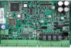
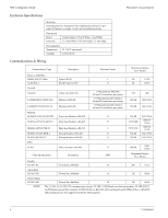
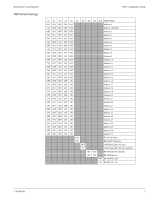
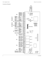
NS2 Configuration Guide Honeywell Access Systems Reader Wiring Each reader port supports a single 12-volt reader with Wiegand output format. Reader 1 Terminal TB3-1 TB3-2 TB3-3 TB3-4 TB3-5 TB3-6 Wire Color Brown Green White Black Red Variable Wiegrand Reader LED Control Data 0 Signal Data 1 Signal Common 12VDC Power Tamper Reader 2 Terminal TB4-1 TB4-2 TB4-3 TB4-4 TB4-5 TB4-6 Wire Color Brown Green White Black Red Variable Wiegrand Reader LED Control Data 0 Signal Data 1 Signal Common 12VDC Power Tamper NS2 version 1.01.01 - 1.03.09 supports only the defaulted Wiegand formats: F=PN 1 26 S 1 D 1 B1 B2 B3 B4 F=PN 2 32 S 0 D 0 B1 B2 B3 B4 F=PN 3 34 S 1 D 1 B1 B2 B3 B4 NOTE: NS2 version 1.01.01 - 1.02.04 at this time does not support the ABA card format, the OL, OJ, and OH Options, Anti- Passback and Lock Down Time. NOTE: NS2 version 1.03.09 does not support the ABA card format or the Lock Down Time option, but does support the NS2MEM module, the OL, OJ, and OH Options, as well as Anti-Passback (In card only mode). Supervised Input Wiring The NS2 supervises inputs 1 through 8 and may be configured for supervised or non-supervised normally open or normally closed contacts. Use standard 1K ohm 5% resistors for supervision. All eight inputs are assigned default features but can be changed for other configurations as needed. Inputs The NS2 has 8 input points located on the following terminals: Input Terminal TB5-1 TB5-3 TB5-2 TB5-4 TB5-6 TB5-5 TB3-6 TB3-5 TB4-6 TB4-4 TB1-3 TB1-1 TB1-2 Description Door 1 Rex Door 1 Status Door 1 & 2 Common Door 2 Rex Door 2 Status Input 3 & 4 Common Reader Tamper or Aux Input 5 Common (Input 5 Common) Reader Tamper or Aux Input 6 Common (Input 6 Common) Power Fail or Aux Input 7 Enclosure Tamper or Aux Input 8 Common (Input 7 & 8 Common) Input/Aux Number 1 2 1 & 2 3 4 3 & 4 5 5 6 6 7 8 7 & 8 NOTE: Tamper and External Power Fail are supervised and capable of being used as additional inputs if the default functionality is not needed. NOTE: The wire used for the inputs should be shielded and cannot exceed 30 ohms over the entire length of the cable. Remember that the distance from the panel to the door must be doubled to determine the total resistance. 2 7-101004-01
-
 1
1 -
 2
2 -
 3
3 -
 4
4 -
 5
5 -
 6
6 -
 7
7 -
 8
8 -
9
-
10
-
11
-
12
-
13
-
14
-
15
-
16
-
17
-
18
-
19
-
20
 |
 |
