Husqvarna 540i XP with battery and charger Owner Manual - Page 14
Assembly, To assemble the guide bar and saw chain, To assemble a spiked bumper
 |
View all Husqvarna 540i XP with battery and charger manuals
Add to My Manuals
Save this manual to your list of manuals |
Page 14 highlights
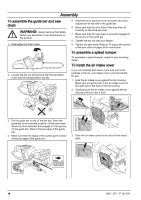
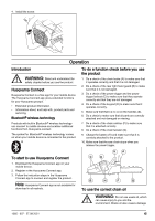
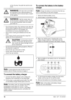
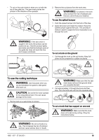
Assembly To assemble the guide bar and saw chain WARNING: Always remove the battery before you assemble or do maintenance on the product. 1. Disengage the chain brake. 2. Loosen the bar nut and remove the drive sprocket cover and the transportation ring (A). 5. Install the drive sprocket cover and steer the chain adjuster pin to the hole in the guide bar. 6. Make sure that the drive links of the saw chain fit correctly on the drive sprocket. 7. Make sure that the saw chain is correctly engaged in the groove in the guide bar. 8. Tighten the bar nut with your fingers. 9. Tighten the saw chain. Refer to To adjust the tension of the saw chain on page 30 for instructions. To assemble a spiked bumper To assemble a spiked bumper, speak to your servicing dealer. To install the air intake cover If you cut materials that cause much dust and small particles in the air, a air intake cover is recommended for use. 1. Hold the air intake cover against the fan housing. Make sure to put the hole in the air intake cover on the right side of the hole in the fan housing. 2. Carefully push the air intake cover against the fan housing until you hear a click. CLICK! A 3. Put the guide bar on top of the bar bolt. Steer the guide bar to its most rear position. Lift the saw chain above the drive sprocket and engage it in the groove on the guide bar. Start on the top edge of the guide bar. 4. Make sure that the edges of the cutters point forward on the top edge of the guide bar. 3. Push the air intake cover to the left until the holes align. 14 1065 - 007 - 27.09.2021
-
 1
1 -
2
-
3
-
4
-
5
-
6
-
7
-
8
-
 9
9 -
 10
10 -
 11
11 -
 12
12 -
 13
13 -
 14
14 -
 15
15 -
 16
16 -
 17
17 -
 18
18 -
 19
19 -
20
-
21
-
22
-
23
-
24
-
25
-
26
-
27
-
28
-
29
-
30
-
31
-
32
-
33
-
34
-
35
-
36
-
37
-
38
-
39
-
40
-
41
-
42
-
43
-
44
-
45
-
46
-
47
-
48
-
49
-
50
-
51
-
52
-
53
-
54
-
55
-
56
-
57
-
58
-
59
-
60
-
61
-
62
-
63
-
64
-
65
-
66
-
67
-
68
-
69
-
70
-
71
-
72
-
73
-
74
-
75
-
76
-
77
-
78
-
79
-
80
-
81
-
82
-
83
-
84
-
85
-
86
-
87
-
88
-
89
-
90
-
91
-
92
-
93
-
94
-
95
-
96
-
97
-
98
-
99
-
100
-
101
-
102
-
103
-
104
-
105
-
106
-
107
-
108
-
109
-
110
-
111
-
112
-
113
-
114
-
115
-
116
-
117
-
118
-
119
-
120
-
121
-
122
-
123
-
124
 |
 |
