IBM 72335LU User Guide - Page 55
connectors
 |
UPC - 883436081535
View all IBM 72335LU manuals
Add to My Manuals
Save this manual to your list of manuals |
Page 55 highlights
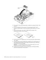
2. Remove the server cover (see "Removing the cover and bezel" on page 28). 3. Make sure that the memory hot-swap enabled LED is lit. If the LED is not lit, enable memory mirroring (see "Active Memory" on page 38). Release latch 4. Remove the memory card: a. Slide the orange release latch to the unlocked position. Attention: v When you move the memory card, do not allow it to touch any components or structures inside the server. v To avoid loss of data, make sure that the memory port power LED is off before you remove the memory card. b. Open the retention levers on the top of the memory card. c. While you hold the retention levers open, lift the memory card out of the server. 5. Place a memory card on a flat, static-protective surface, with the DIMM connectors facing up. Attention: To avoid breaking the DIMM retaining clips or damaging the DIMM connectors, open and close the clips gently. 6. Open the retaining clip on each end of the DIMM connector and remove the DIMM or DIMMs that you are replacing. 7. Touch the static-protective package that contains the DIMM to any unpainted metal surface on the outside of the server; then, remove the DIMM from the package. 8. Turn the DIMM so that the DIMM keys align correctly with the slot. 9. Insert the DIMM into the connector by aligning the edges of the DIMM with the slots at the ends of the DIMM connector. Firmly press one end of the DIMM into the connector; then, press the other end into the connector. The retaining clips snap into the locked position when the DIMM is seated in the connector. Chapter 2. Installing optional devices 43
-
 1
1 -
2
-
3
-
4
-
5
-
6
-
7
-
8
-
9
-
10
-
11
-
12
-
13
-
14
-
15
-
16
-
17
-
18
-
19
-
20
-
21
-
22
-
23
-
24
-
25
-
26
-
27
-
28
-
29
-
30
-
31
-
32
-
33
-
34
-
35
-
36
-
37
-
38
-
39
-
40
-
41
-
42
-
43
-
44
-
45
-
46
-
47
-
48
-
49
-
 50
50 -
 51
51 -
 52
52 -
 53
53 -
 54
54 -
 55
55 -
 56
56 -
 57
57 -
 58
58 -
 59
59 -
 60
60 -
61
-
62
-
63
-
64
-
65
-
66
-
67
-
68
-
69
-
70
-
71
-
72
-
73
-
74
-
75
-
76
-
77
-
78
-
79
-
80
-
81
-
82
-
83
-
84
-
85
-
86
-
87
-
88
-
89
-
90
-
91
-
92
-
93
-
94
-
95
-
96
 |
 |
