IBM 72335LU User Guide - Page 59
electricity.
 |
UPC - 883436081535
View all IBM 72335LU manuals
Add to My Manuals
Save this manual to your list of manuals |
Page 59 highlights
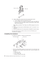
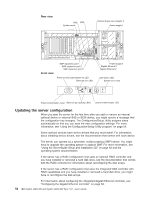
Fan 4 Fan 1 V R M 3 CPU 3 Fan 5 Fan 2 CPU 4 Fan 6 Fan 3 V R M 4 Memory Cards V R 1 2M 1 CPU 1 CPU 2 V R Memory Cards M3 4 2 2. Microprocessor socket 2 must always contain either a heat-sink blank or a microprocessor and heat sink. 3. The microprocessor air-baffle must always be installed between microprocessor socket 1 and socket 2. To install a microprocessor, complete the following steps: 1. Read the safety information that begins on page v and "Installation guidelines" on page 26. 2. Turn off the server and peripheral devices, and disconnect the power cords and all external cables as necessary to replace the device. 3. Remove the server cover and bezel (see "Removing the cover and bezel" on page 28). Attention: When you handle static-sensitive devices, take precautions to avoid damage from static electricity. For details about handling these devices, see "Handling static-sensitive devices" on page 28. 4. Loosen the captive screws and rotate the media hood to the fully open position. Chapter 2. Installing optional devices 47
-
 1
1 -
2
-
3
-
4
-
5
-
6
-
7
-
8
-
9
-
10
-
11
-
12
-
13
-
14
-
15
-
16
-
17
-
18
-
19
-
20
-
21
-
22
-
23
-
24
-
25
-
26
-
27
-
28
-
29
-
30
-
31
-
32
-
33
-
34
-
35
-
36
-
37
-
38
-
39
-
40
-
41
-
42
-
43
-
44
-
45
-
46
-
47
-
48
-
49
-
50
-
51
-
52
-
53
-
 54
54 -
 55
55 -
 56
56 -
 57
57 -
 58
58 -
 59
59 -
 60
60 -
 61
61 -
 62
62 -
 63
63 -
 64
64 -
65
-
66
-
67
-
68
-
69
-
70
-
71
-
72
-
73
-
74
-
75
-
76
-
77
-
78
-
79
-
80
-
81
-
82
-
83
-
84
-
85
-
86
-
87
-
88
-
89
-
90
-
91
-
92
-
93
-
94
-
95
-
96
 |
 |
