IBM 72335LU User Guide - Page 61
microprocessor
 |
UPC - 883436081535
View all IBM 72335LU manuals
Add to My Manuals
Save this manual to your list of manuals |
Page 61 highlights
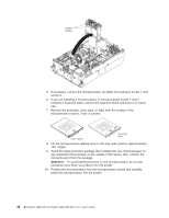
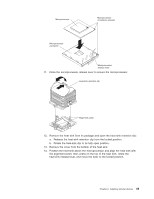
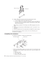
Microprocessor Microprocessor orientation indicator Microprocessor connector Microprocessorrelease lever 11. Close the microprocessor-release lever to secure the microprocessor. Heat-sink retention clip Alignment posts 12. Remove the heat sink from its package and open the heat-sink retention clip: a. Release the heat-sink retention clip from the locked position. b. Rotate the heat-sink clip to its fully open position. 13. Remove the cover from the bottom of the heat sink. 14. Position the heat sink above the microprocessor and align the heat sink with the alignment posts; then, press on the top of the heat sink, rotate the heat-sink release lever, and move the lever to the locked position. Chapter 2. Installing optional devices 49
-
 1
1 -
2
-
3
-
4
-
5
-
6
-
7
-
8
-
9
-
10
-
11
-
12
-
13
-
14
-
15
-
16
-
17
-
18
-
19
-
20
-
21
-
22
-
23
-
24
-
25
-
26
-
27
-
28
-
29
-
30
-
31
-
32
-
33
-
34
-
35
-
36
-
37
-
38
-
39
-
40
-
41
-
42
-
43
-
44
-
45
-
46
-
47
-
48
-
49
-
50
-
51
-
52
-
53
-
54
-
55
-
 56
56 -
 57
57 -
 58
58 -
 59
59 -
 60
60 -
 61
61 -
 62
62 -
 63
63 -
 64
64 -
 65
65 -
 66
66 -
67
-
68
-
69
-
70
-
71
-
72
-
73
-
74
-
75
-
76
-
77
-
78
-
79
-
80
-
81
-
82
-
83
-
84
-
85
-
86
-
87
-
88
-
89
-
90
-
91
-
92
-
93
-
94
-
95
-
96
 |
 |

Microprocessor
orientation indicator
Microprocessor-
release lever
Microprocessor
connector
Microprocessor
11.
Close
the
microprocessor-release
lever
to
secure
the
microprocessor.
Alignment posts
Heat-sink retention clip
12.
Remove
the
heat
sink
from
its
package
and
open
the
heat-sink
retention
clip:
a.
Release
the
heat-sink
retention
clip
from
the
locked
position.
b.
Rotate
the
heat-sink
clip
to
its
fully
open
position.
13.
Remove
the
cover
from
the
bottom
of
the
heat
sink.
14.
Position
the
heat
sink
above
the
microprocessor
and
align
the
heat
sink
with
the
alignment
posts;
then,
press
on
the
top
of
the
heat
sink,
rotate
the
heat-sink
release
lever,
and
move
the
lever
to
the
locked
position.
Chapter
2.
Installing
optional
devices
49