IBM IC35L040AVVN07-0 Hard Drive Specifications - Page 13
S.M.A.R.T. Function Set Command B0h
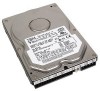 |
UPC - 683728124212
View all IBM IC35L040AVVN07-0 manuals
Add to My Manuals
Save this manual to your list of manuals |
Page 13 highlights
Figure 104. Identify Device Information (part 5 of 6 121 Figure 105. Identify Device Information (part 6 of 6 122 Figure 106. Idle Command (E3h/97h 123 Figure 107. Idle Immediate Command (E1h/95h 124 Figure 108. Initialize Device Parameters Command (91h 125 Figure 109. NOP Command (00h 126 Figure 110. Read Buffer Command (E4h 127 Figure 111. Read DMA Command (C8h/C9h 128 Figure 112. Read DMA Queued Command (C7h 130 Figure 113. Read Long Command (22h/23h 132 Figure 114. Read Multiple Command (C4h 134 Figure 115. Read Native Max LBA/CYL (F8h 136 Figure 116. Read Sectors Command (20h/21h 137 Figure 117. Read Verify Sectors Command (40h/41h 139 Figure 118. Recalibrate Command (1xh 141 Figure 119. Security Disable Password Command (F6h 142 Figure 120. Password Information for Security Disable Password command 142 Figure 121. Security Erase Prepare Command (F3h 143 Figure 122. Security Erase Unit Command (F4h 144 Figure 123. Erase Unit Information 144 Figure 124. Security Freeze Lock Command (F5h 146 Figure 125. Security Set Password Command (F1h 147 Figure 126. Security Set Password Information 148 Figure 127. Security Unlock Command (F2h 149 Figure 128. Security Unlock Information 150 Figure 129. Seek Command (7xh 151 Figure 130. Service Command (A2h 152 Figure 131. Set Features Command (EFh 153 Figure 132. Set Max Address (F9h 156 Figure 133. Set Max Set Password 158 Figure 134. Set Max Set Password data contents 158 Figure 135. Set Max Lock 159 Figure 136. Set Max Unlock (F9h 160 Figure 137. Set Max Freeze Lock (F9h 161 Figure 138. Set Multiple Command (C6h 162 Figure 139. Sleep Command (E6h/99h 163 Figure 140. S.M.A.R.T. Function Set Command (B0h 164 Figure 141. Log sector addresses 166 Figure 142. Device Attributes Data Structure 168 Figure 143. Individual Attribute Data Structure 169 Figure 144. Device Attribute Thresholds Data Structure 172 Figure 145. Individual Threshold Data Structure 172 Figure 146. SMART error log sector 173 Figure 147. Error log data structure 174 Figure 148. Command data structure 174 Figure 149. Error data structure 175 Figure 150. Self-test log data structure 176 Figure 151. S.M.A.R.T. Error Codes 177 Figure 152. Standby Command (E2h/96h 178 Figure 153. Standby Immediate Command (E0h/94h 180 Figure 154. Write Buffer Command (E8h 181 Figure 155. Write DMA Command (CAh/CBh 182 Figure 156. Write DMA Queued Command (CCh 184 Figure 157. Write Long Command (32h/33h 186 Deskstar 120GXP hard disk drive specifications xi
-
 1
1 -
2
-
3
-
4
-
5
-
6
-
7
-
 8
8 -
 9
9 -
 10
10 -
 11
11 -
 12
12 -
 13
13 -
 14
14 -
 15
15 -
 16
16 -
 17
17 -
 18
18 -
19
-
20
-
21
-
22
-
23
-
24
-
25
-
26
-
27
-
28
-
29
-
30
-
31
-
32
-
33
-
34
-
35
-
36
-
37
-
38
-
39
-
40
-
41
-
42
-
43
-
44
-
45
-
46
-
47
-
48
-
49
-
50
-
51
-
52
-
53
-
54
-
55
-
56
-
57
-
58
-
59
-
60
-
61
-
62
-
63
-
64
-
65
-
66
-
67
-
68
-
69
-
70
-
71
-
72
-
73
-
74
-
75
-
76
-
77
-
78
-
79
-
80
-
81
-
82
-
83
-
84
-
85
-
86
-
87
-
88
-
89
-
90
-
91
-
92
-
93
-
94
-
95
-
96
-
97
-
98
-
99
-
100
-
101
-
102
-
103
-
104
-
105
-
106
-
107
-
108
-
109
-
110
-
111
-
112
-
113
-
114
-
115
-
116
-
117
-
118
-
119
-
120
-
121
-
122
-
123
-
124
-
125
-
126
-
127
-
128
-
129
-
130
-
131
-
132
-
133
-
134
-
135
-
136
-
137
-
138
-
139
-
140
-
141
-
142
-
143
-
144
-
145
-
146
-
147
-
148
-
149
-
150
-
151
-
152
-
153
-
154
-
155
-
156
-
157
-
158
-
159
-
160
-
161
-
162
-
163
-
164
-
165
-
166
-
167
-
168
-
169
-
170
-
171
-
172
-
173
-
174
-
175
-
176
-
177
-
178
-
179
-
180
-
181
-
182
-
183
-
184
-
185
-
186
-
187
-
188
-
189
-
190
-
191
-
192
-
193
-
194
-
195
-
196
-
197
-
198
-
199
-
200
-
201
-
202
-
203
-
204
-
205
-
206
-
207
-
208
-
209
-
210
-
211
 |
 |
