IBM IC35L040AVVN07-0 Hard Drive Specifications - Page 84
Device/Head Register, Error Register
 |
UPC - 683728124212
View all IBM IC35L040AVVN07-0 manuals
Add to My Manuals
Save this manual to your list of manuals |
Page 84 highlights
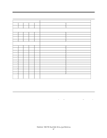
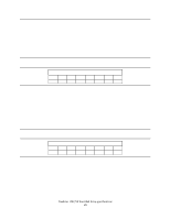
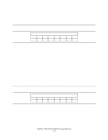
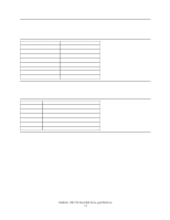
-DS1 -DS0 -Drive Select 1. Drive select bit for device 1, active low. DS1=0 when device 1 (slave) is selected and active. -Drive Select 0. Drive select bit for device 0, active low. DS0=0 when device 0 (master) is selected and active. 8.8 Device/Head Register Device/Head Register 7 6 5 4 3 2 1 0 1 L 1 DRV HS3 HS2 HS1 HS0 Figure 72. Device/Head Register This register contains the device and head numbers. Bit Definitions L Binary encoded address mode select. When L=0, addressing is by CHS mode. When L=1, addressing is by LBA mode. DRV Device. When DRV=0, device 0 (master) is selected. When DRV=1, device 1 (slave) is selected. HS3, HS2, HS1, HS0 Head Select. These four bits indicate binary encoded address of the head. HS0 is the least significant bit. At command completion these bits are updated to reflect the currently selected head. The head number may be from zero to the number of heads minus one. In LBA mode HS3 through HS0 contain bits 24-27 of the LBA. At command completion these bits are updated to reflect the current LBA bits 24-27. 8.9 Error Register 7 6 CRC UNC Error Register 5 4 3 2 1 0 0 IDNF 0 ABRT TK0NF AMNF Figure 73. Error Register This register contains status from the last command executed by the device or a diagnostic code. At the completion of any command - except Execute Device Diagnostic - the contents of this register are always valid even if ERR=0 is in the Status Register. Following a power on, a reset, or completion of an Execute Device Diagnostic command, this register contains a diagnostic code. See Figure 77 on page 74 for the definition. Deskstar 120GXP hard disk drive specifications 70
-
 1
1 -
2
-
3
-
4
-
5
-
6
-
7
-
8
-
9
-
10
-
11
-
12
-
13
-
14
-
15
-
16
-
17
-
18
-
19
-
20
-
21
-
22
-
23
-
24
-
25
-
26
-
27
-
28
-
29
-
30
-
31
-
32
-
33
-
34
-
35
-
36
-
37
-
38
-
39
-
40
-
41
-
42
-
43
-
44
-
45
-
46
-
47
-
48
-
49
-
50
-
51
-
52
-
53
-
54
-
55
-
56
-
57
-
58
-
59
-
60
-
61
-
62
-
63
-
64
-
65
-
66
-
67
-
68
-
69
-
70
-
71
-
72
-
73
-
74
-
75
-
76
-
77
-
78
-
 79
79 -
 80
80 -
 81
81 -
 82
82 -
 83
83 -
 84
84 -
 85
85 -
 86
86 -
 87
87 -
 88
88 -
 89
89 -
90
-
91
-
92
-
93
-
94
-
95
-
96
-
97
-
98
-
99
-
100
-
101
-
102
-
103
-
104
-
105
-
106
-
107
-
108
-
109
-
110
-
111
-
112
-
113
-
114
-
115
-
116
-
117
-
118
-
119
-
120
-
121
-
122
-
123
-
124
-
125
-
126
-
127
-
128
-
129
-
130
-
131
-
132
-
133
-
134
-
135
-
136
-
137
-
138
-
139
-
140
-
141
-
142
-
143
-
144
-
145
-
146
-
147
-
148
-
149
-
150
-
151
-
152
-
153
-
154
-
155
-
156
-
157
-
158
-
159
-
160
-
161
-
162
-
163
-
164
-
165
-
166
-
167
-
168
-
169
-
170
-
171
-
172
-
173
-
174
-
175
-
176
-
177
-
178
-
179
-
180
-
181
-
182
-
183
-
184
-
185
-
186
-
187
-
188
-
189
-
190
-
191
-
192
-
193
-
194
-
195
-
196
-
197
-
198
-
199
-
200
-
201
-
202
-
203
-
204
-
205
-
206
-
207
-
208
-
209
-
210
-
211
 |
 |
