IBM IC35L040AVVN07-0 Hard Drive Specifications - Page 39
Interface logic signal levels
 |
UPC - 683728124212
View all IBM IC35L040AVVN07-0 manuals
Add to My Manuals
Save this manual to your list of manuals |
Page 39 highlights
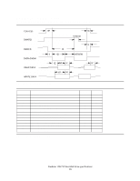
DDMARDY- (Ultra DMA) This signal is used only for Ultra DMA data transfers between the host and the device. DDMARDY- is a flow control signal for Ultra DMA data out bursts. This signal is held asserted by the device to indicate to the host that the device is ready to receive Ultra DMA data out transfers. The device may negate DDMARDY- to pause an Ultra DMA data out transfer. DSTROBE (Ultra DMA) This signal is used only for Ultra DMA data transfers between the host and the device. DSTROBE is the data in strobe signal from the device for an Ultra DMA data in transfer. Both the rising and falling edge of DSTROBE latch the data from DD(15:0) into the host. The device may stop toggling DSTROBE to pause an Ultra DMA data in transfer. Device Termination The termination resistors on the device side are implemented on the drive side as follows: !33 Ω for DD0 thru DD15, DMARQ, INTRQ !82 Ω for CS0-, CS1-, DA0, DA1, DA2, DIOR-, DIOW-, DMACK!22 Ω for IORDY 6.1.3 Interface logic signal levels The interface logic signal has the following electrical specifications: Inputs Input High Voltage Input Low Voltage Outputs Output High Voltage Output Low Voltage 2.0 V min. 0.8 V max. 2.4 V min. 0.5 V max. Deskstar 120GXP hard disk drive specifications 25
-
 1
1 -
2
-
3
-
4
-
5
-
6
-
7
-
8
-
9
-
10
-
11
-
12
-
13
-
14
-
15
-
16
-
17
-
18
-
19
-
20
-
21
-
22
-
23
-
24
-
25
-
26
-
27
-
28
-
29
-
30
-
31
-
32
-
33
-
 34
34 -
 35
35 -
 36
36 -
 37
37 -
 38
38 -
 39
39 -
 40
40 -
 41
41 -
 42
42 -
 43
43 -
 44
44 -
45
-
46
-
47
-
48
-
49
-
50
-
51
-
52
-
53
-
54
-
55
-
56
-
57
-
58
-
59
-
60
-
61
-
62
-
63
-
64
-
65
-
66
-
67
-
68
-
69
-
70
-
71
-
72
-
73
-
74
-
75
-
76
-
77
-
78
-
79
-
80
-
81
-
82
-
83
-
84
-
85
-
86
-
87
-
88
-
89
-
90
-
91
-
92
-
93
-
94
-
95
-
96
-
97
-
98
-
99
-
100
-
101
-
102
-
103
-
104
-
105
-
106
-
107
-
108
-
109
-
110
-
111
-
112
-
113
-
114
-
115
-
116
-
117
-
118
-
119
-
120
-
121
-
122
-
123
-
124
-
125
-
126
-
127
-
128
-
129
-
130
-
131
-
132
-
133
-
134
-
135
-
136
-
137
-
138
-
139
-
140
-
141
-
142
-
143
-
144
-
145
-
146
-
147
-
148
-
149
-
150
-
151
-
152
-
153
-
154
-
155
-
156
-
157
-
158
-
159
-
160
-
161
-
162
-
163
-
164
-
165
-
166
-
167
-
168
-
169
-
170
-
171
-
172
-
173
-
174
-
175
-
176
-
177
-
178
-
179
-
180
-
181
-
182
-
183
-
184
-
185
-
186
-
187
-
188
-
189
-
190
-
191
-
192
-
193
-
194
-
195
-
196
-
197
-
198
-
199
-
200
-
201
-
202
-
203
-
204
-
205
-
206
-
207
-
208
-
209
-
210
-
211
 |
 |
