IBM IC35L040AVVN07-0 Hard Drive Specifications - Page 44
Ultra DMA timings
 |
UPC - 683728124212
View all IBM IC35L040AVVN07-0 manuals
Add to My Manuals
Save this manual to your list of manuals |
Page 44 highlights
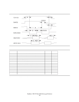
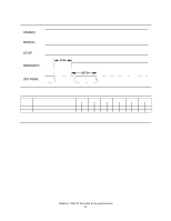
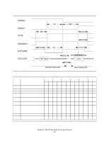
6.2.4 Ultra DMA timings The Ultra DMA timing meets Mode 0,1,2,3 4, and 5 of the Ultra DMA Protocol. 6.2.4.1 Initiating Read DMA DMARQ DMACKSTOP tUI tACK tENV tACK tENV HDMARDY- tZIORDY DSTROBE DD(15:00) tAZ xxxxxxxxxxxxxxxxxxxxxxxxx Host drives DD t2CYC tFS tDZFS tCYC tCYC tZAD tDS tDH tDS tDH xxx RD Data xxx RD Data xxx RD Data Device drives DD Figure 27. Ultra DMA cycle timing chart (Initiating Read) tUI tACK tENV tZIORDY tFS tCYC t2CYC tAZ tZAD tDS tDH tDZFS PARAMETER DESCRIPTION (all values in ns) Unlimited interlock time Setup time before -DMACK Envelope time Minimum time before driving IORDY First DSTROBE time Cycle time Two cycle time Maximum time allowed for output drivers to release Maximum time allowed for output drivers to assert Data setup time (at host) Data hold time (at host) Time from data output released-to-driving until the first transition of critical timing MODE0 MODE1 MODE2 MODE3 MODE4 MODE5 MIN MAX MIN MAX MIN MAX MIN MAX MIN MAX MIN MAX 0-0-000-0-0 - 20 - 20 - 20 - 20 - 20 - 20 - 20 70 20 70 20 70 20 55 20 55 20 50 0-0-0-0-0-0 - 0 230 0 200 0 170 0 130 0 120 0 90 112 - 73 - 54 - 39 - 25 - 17 - 230 - 153 - 115 - 86 - 57 - 38 - - 10 - 10 - 10 - 10 - 10 - 10 0-0-0-0-0-0 - 15 - 10 - 7 - 7 - 5 - 4 - 5 - 5 - 5 - 5 - 5 - 4.6 - 70 - 48 - 31 - 20 - 6.7 - 25 - Figure 28. Ultra DMA cycle timings (Initiating Read) Deskstar 120GXP hard disk drive specifications 30
-
 1
1 -
2
-
3
-
4
-
5
-
6
-
7
-
8
-
9
-
10
-
11
-
12
-
13
-
14
-
15
-
16
-
17
-
18
-
19
-
20
-
21
-
22
-
23
-
24
-
25
-
26
-
27
-
28
-
29
-
30
-
31
-
32
-
33
-
34
-
35
-
36
-
37
-
38
-
 39
39 -
 40
40 -
 41
41 -
 42
42 -
 43
43 -
 44
44 -
 45
45 -
 46
46 -
 47
47 -
 48
48 -
 49
49 -
50
-
51
-
52
-
53
-
54
-
55
-
56
-
57
-
58
-
59
-
60
-
61
-
62
-
63
-
64
-
65
-
66
-
67
-
68
-
69
-
70
-
71
-
72
-
73
-
74
-
75
-
76
-
77
-
78
-
79
-
80
-
81
-
82
-
83
-
84
-
85
-
86
-
87
-
88
-
89
-
90
-
91
-
92
-
93
-
94
-
95
-
96
-
97
-
98
-
99
-
100
-
101
-
102
-
103
-
104
-
105
-
106
-
107
-
108
-
109
-
110
-
111
-
112
-
113
-
114
-
115
-
116
-
117
-
118
-
119
-
120
-
121
-
122
-
123
-
124
-
125
-
126
-
127
-
128
-
129
-
130
-
131
-
132
-
133
-
134
-
135
-
136
-
137
-
138
-
139
-
140
-
141
-
142
-
143
-
144
-
145
-
146
-
147
-
148
-
149
-
150
-
151
-
152
-
153
-
154
-
155
-
156
-
157
-
158
-
159
-
160
-
161
-
162
-
163
-
164
-
165
-
166
-
167
-
168
-
169
-
170
-
171
-
172
-
173
-
174
-
175
-
176
-
177
-
178
-
179
-
180
-
181
-
182
-
183
-
184
-
185
-
186
-
187
-
188
-
189
-
190
-
191
-
192
-
193
-
194
-
195
-
196
-
197
-
198
-
199
-
200
-
201
-
202
-
203
-
204
-
205
-
206
-
207
-
208
-
209
-
210
-
211
 |
 |
