InSinkErator Invite H990-SS Owners Manual - Page 7
Installing The Faucet - Hc3/gn3
 |
View all InSinkErator Invite H990-SS manuals
Add to My Manuals
Save this manual to your list of manuals |
Page 7 highlights
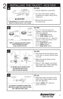
2 INSTALLING THE FAUCET - HC3/ GN3 A HC3 / GN3 I Unpack dispenser components. I On a firm, flat surface, carefully straighten the copper tubing using hands only. Property Damage: Do not pinch or break copper tubing. Do not distort the last 1 inch of tubing. I Remove the wing nut from the valve body. B 15⁄8" Small Steel Washer 15⁄8" Small Rubber Washer 15⁄8" Small Steel Washer 15⁄8" Rubber Washer 21⁄4" Large Steel Washer 11⁄4" Hole Hole larger than 11⁄4" BOTH 15⁄8" small steel and rubber washers MUST BE INSTALLED to ensure proper operation and seal. HC3 / GN3 I For a 11⁄4" sink hole, place the washers on the faucet base in this order (see diagram): 1) 15⁄8" small steel washer 2) 15⁄8" small rubber washer. I For a hole larger than 11⁄4", place the washers on the facuet base in this order (see diagram): 1) 15⁄8" small steel washer 2) 15⁄8" rubber washer 3) 21⁄4" large steel washer C Fiber Washer Wing Nut An assistant may be needed to hold the dispenser head in place while securing the dispenser. HC3 / GN3 I Feed tubes down through the hole in the sink or counter until the base is at rest. I Make sure faucet head is at the desired angle. I Slide 21⁄4" fiber washer over faucet base under sink. Tighten assembly using black plastic wing nut. D From faucet 3/8" white tube An extension is available by special order (EXT-10) for counters more than 3/4" thick. Call 1-800-558-5700 to order. HC3 only I Attach the quick connector to the ends of the copper tubes running from the dispenser. I Install a white 3/8" tube into quick connector. I 7
-
 1
1 -
 2
2 -
 3
3 -
 4
4 -
 5
5 -
 6
6 -
 7
7 -
 8
8 -
 9
9 -
 10
10 -
 11
11 -
 12
12 -
13
-
14
-
15
-
16
-
17
-
18
-
19
-
20
-
21
-
22
-
23
-
24
-
25
-
26
-
27
-
28
-
29
-
30
-
31
-
32
-
33
-
34
-
35
-
36
-
37
-
38
-
39
-
40
-
41
-
42
-
43
 |
 |
