Intel Q9300 Data Sheet - Page 81
Processor Thermal Features
 |
UPC - 675900938236
View all Intel Q9300 manuals
Add to My Manuals
Save this manual to your list of manuals |
Page 81 highlights
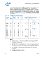
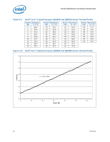
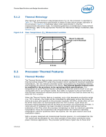
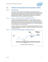
Thermal Specifications and Design Considerations 5.1.2 Thermal Metrology The maximum and minimum case temperatures (TC) for the processor is specified in Table 5-1. This temperature specification is meant to help ensure proper operation of the processor. Figure 5-5 illustrates where Intel recommends TC thermal measurements should be made. For detailed guidelines on temperature measurement methodology, refer to the appropriate Thermal and Mechanical Design Guidelines (See Section 1.2). Figure 5-5. Case Temperature (TC) Measurement Location Measure TC at this point (geometric center of the package) 37.5 mm 5.2 5.2.1 37.5 mm Processor Thermal Features Thermal Monitor The Thermal Monitor feature helps control the processor temperature by activating the thermal control circuit (TCC) when the processor silicon reaches its maximum operating temperature. The TCC reduces processor power consumption by modulating (starting and stopping) the internal processor core clocks. The Thermal Monitor feature must be enabled for the processor to be operating within specifications. The temperature at which Thermal Monitor activates the thermal control circuit is not user configurable and is not software visible. Bus traffic is snooped in the normal manner, and interrupt requests are latched (and serviced during the time that the clocks are on) while the TCC is active. When the Thermal Monitor feature is enabled, and a high temperature situation exists (i.e., TCC is active), the clocks will be modulated by alternately turning the clocks off and on at a duty cycle specific to the processor (typically 30-50%). Clocks often will not be off for more than 3.0 microseconds when the TCC is active. Cycle times are processor speed dependent and will decrease as processor core frequencies increase. A small amount of hysteresis has been included to prevent rapid active/inactive transitions of the TCC when the processor temperature is near its maximum operating temperature. Once the temperature has dropped below the maximum operating temperature, and the hysteresis timer has expired, the TCC goes inactive and clock modulation ceases. With a properly designed and characterized thermal solution, it is anticipated that the TCC would only be activated for very short periods of time when running the most power intensive applications. The processor performance impact due to these brief Datasheet 81
-
 1
1 -
2
-
3
-
4
-
5
-
6
-
7
-
8
-
9
-
10
-
11
-
12
-
13
-
14
-
15
-
16
-
17
-
18
-
19
-
20
-
21
-
22
-
23
-
24
-
25
-
26
-
27
-
28
-
29
-
30
-
31
-
32
-
33
-
34
-
35
-
36
-
37
-
38
-
39
-
40
-
41
-
42
-
43
-
44
-
45
-
46
-
47
-
48
-
49
-
50
-
51
-
52
-
53
-
54
-
55
-
56
-
57
-
58
-
59
-
60
-
61
-
62
-
63
-
64
-
65
-
66
-
67
-
68
-
69
-
70
-
71
-
72
-
73
-
74
-
75
-
 76
76 -
 77
77 -
 78
78 -
 79
79 -
 80
80 -
 81
81 -
 82
82 -
 83
83 -
 84
84 -
 85
85 -
 86
86 -
87
-
88
-
89
-
90
-
91
-
92
-
93
-
94
-
95
-
96
-
97
-
98
-
99
-
100
-
101
-
102
-
103
-
104
 |
 |
