Intel WX58BP Product Guide - Page 35
Installing and Removing Memory
 |
UPC - 735858208864
View all Intel WX58BP manuals
Add to My Manuals
Save this manual to your list of manuals |
Page 35 highlights
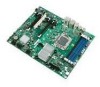
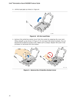
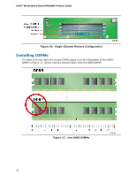
Updating the BIOS Installing and Removing Memory The Intel® Workstation Board WX58BP has four 240-pin DDR3 DIMM sockets arranged in three channels (A, B, and C). Channel A shares two sockets (DIMM 0 and DIMM 1) and Channels B and C have one socket each. Guidelines for Memory Configuration Before installing DIMMs, read and follow these guidelines for memory configuration. You can achieve optimal memory performance by installing three matched DIMMS of equal speed and size in the blue DIMM slots (Channel A, DIMM 0, Channel B, and Channel C) as shown in Figure 14. Figure 14. Triple Channel Memory Configuration NOTE Installing memory in Channel A, DIMM 1 may result in less than optimal memory performance. To obtain dual channel memory operation, install matching DIMMs as shown in Figure 15. A typical single channel configuration is shown in Figure 16. Figure 15. Dual Channel Memory Configuration 35
-
 1
1 -
2
-
3
-
4
-
5
-
6
-
7
-
8
-
9
-
10
-
11
-
12
-
13
-
14
-
15
-
16
-
17
-
18
-
19
-
20
-
21
-
22
-
23
-
24
-
25
-
26
-
27
-
28
-
29
-
 30
30 -
 31
31 -
 32
32 -
 33
33 -
 34
34 -
 35
35 -
 36
36 -
 37
37 -
 38
38 -
 39
39 -
 40
40 -
41
-
42
-
43
-
44
-
45
-
46
-
47
-
48
-
49
-
50
-
51
-
52
-
53
-
54
-
55
-
56
-
57
-
58
-
59
-
60
-
61
-
62
-
63
-
64
-
65
-
66
-
67
-
68
-
69
-
70
-
71
-
72
-
73
-
74
-
75
-
76
-
77
-
78
 |
 |