Intel WX58BP Product Guide - Page 47
Alternate Front Panel Power LED Header, S/PDIF Connector
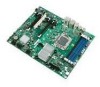 |
UPC - 735858208864
View all Intel WX58BP manuals
Add to My Manuals
Save this manual to your list of manuals |
Page 47 highlights
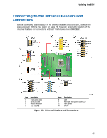
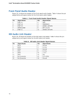
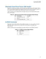
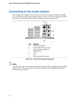
Updating the BIOS Alternate Front Panel Power LED Header Figure 23, H shows the location of the alternate front panel power LED header. Pins 1 and 3 of this header duplicate the signals on pins 2 and 4 of the front panel header. If your chassis has a three-pin power LED cable, connect it to this header. Table 10 shows the pin assignments and signal names for the alternate front panel power LED header. Table 10. Alternate Front Panel Power LED Header Signal Names Pin Description 1 Front panel green LED 2 No pin 3 Front panel yellow LED In/Out Out Out S/PDIF Connector Figure 23, J shows the location of the S/PDIF connector. You can use this connector with HDMI video cards that do not work with the HD Audio Link header (see Figure 23, B). Table 11 shows the pin assignments and signal names for the S/PDIF connector. Table 11. S/PDIF Connector Signal Names Pin Description 1 Vcc 2 S/PDIF Out 3 Ground 47
-
 1
1 -
2
-
3
-
4
-
5
-
6
-
7
-
8
-
9
-
10
-
11
-
12
-
13
-
14
-
15
-
16
-
17
-
18
-
19
-
20
-
21
-
22
-
23
-
24
-
25
-
26
-
27
-
28
-
29
-
30
-
31
-
32
-
33
-
34
-
35
-
36
-
37
-
38
-
39
-
40
-
41
-
 42
42 -
 43
43 -
 44
44 -
 45
45 -
 46
46 -
 47
47 -
 48
48 -
 49
49 -
 50
50 -
 51
51 -
 52
52 -
53
-
54
-
55
-
56
-
57
-
58
-
59
-
60
-
61
-
62
-
63
-
64
-
65
-
66
-
67
-
68
-
69
-
70
-
71
-
72
-
73
-
74
-
75
-
76
-
77
-
78
 |
 |
