Invacare IN66AHANFR Owners Manual - Page 36
Wheel Locks
 |
View all Invacare IN66AHANFR manuals
Add to My Manuals
Save this manual to your list of manuals |
Page 36 highlights
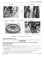
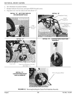
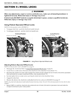
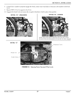
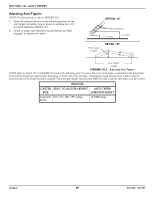
SECTION 9-WHEEL LOCKS SECTION 9-WHEEL LOCKS ƽ WARNING After any adjustments, repair or service and before use, make sure all attaching hardware is tightened securely. Otherwise injury or damage may occur. If wheel locks DO NOT hold the occupied wheelchair in place, contact a qualified technician. Otherwise injury or damage may occur. Using Patient Operated Wheel Locks NOTE: For this procedure, refer to FIGURE 9.1. 1. To engage wheel lock ‐ push the wheel lock handle forward. 2. To disengage wheel lock ‐ pull the wheel lock handle back. Unlocked Position Wheel Lock Handle Locked Position Wheel Lock Handle FIGURE 9.1 Using Patient Operated Wheel Locks Adjusting Patient-Operated Wheel Locks NOTE: For this procedure, refer to FIGURE 9.2 on page 37. 1. Disengage the wheel locks. Refer to Using Patient Operated Wheel Locks on page 36. 2. Loosen the two socket screws that secure the wheel lock to the wheelchair frame (Detail "C"). 3. Reposition the wheel lock so that when engaged, the wheel lock shoe embeds the tire 1/8‐inch (3/16‐inch for pneumatic tires) and holds the occupied wheelchair in place when pushed (Detail "B"). 4. Securely tighten the two socket screws securing the wheel lock to the wheelchair frame. 5. Engage the wheel lock. 6. Measure the distance the wheel lock is embedded into the tire as shown in FIGURE 9.2 on page 37. NOTE: Any wheel lock adjustment should embed the wheel lock shoe at least 1/8‐inch (3/16‐inch if pneumatic tire) into the tire when engaged. 7. Repeat STEPS 1‐6 until the wheel lock shoe embeds the tire 1/8‐inch (3/16‐inch for pneumatic tires) and holds the occupied wheelchair in place when pushed. Insignia™ 36 Part No. 1163197
-
 1
1 -
2
-
3
-
4
-
5
-
6
-
7
-
8
-
9
-
10
-
11
-
12
-
13
-
14
-
15
-
16
-
17
-
18
-
19
-
20
-
21
-
22
-
23
-
24
-
25
-
26
-
27
-
28
-
29
-
30
-
 31
31 -
 32
32 -
 33
33 -
 34
34 -
 35
35 -
 36
36 -
 37
37 -
 38
38 -
 39
39 -
 40
40 -
 41
41 -
42
-
43
-
44
-
45
-
46
-
47
-
48
-
49
-
50
-
51
-
52
 |
 |
