JVC GY-DV300REM Instruction Manual - Page 29
Angle of View (Zoom In/ Zoom Out), Menu Screen Settings
 |
View all JVC GY-DV300REM manuals
Add to My Manuals
Save this manual to your list of manuals |
Page 29 highlights
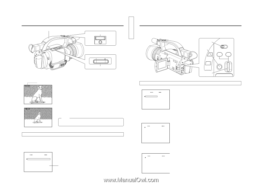
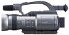
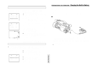
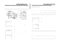
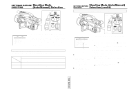
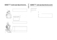
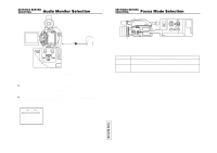
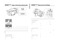
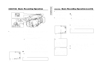
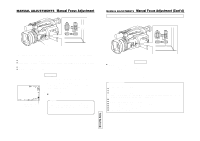
SETTINGS BEFORE SHOOTING Angle of View (Zoom In/Zoom Out) Handle ZOOM lever T W START/ STOP W VOLUME T ZOOM lever The ZOOM lever is used for zoom-in and zoom-out operations. Zooming can be performed using either the ZOOM lever on the top section of the GY-DV300 or the ZOOM lever on the top of the handle section. Zoom operation indication Zoom-in : The subject becomes larger (max. 14 times) Zoom-out : The subject becomes smaller and the picture angle wider. Memo: During zooming, the zoom position and zoom ratio are indicated on the LCD screen and the viewfinder screen. Zooming Ⅲ Set the MODE switch to "CAM-A" or "CAM-B". Ⅲ To zoom in, press the ZOOM lever toward the "T" side. Ⅲ To zoom out, press the ZOOM lever toward the "W" side. SYSTEM [2/2] menu screen SY STEM[ 2 / 2 ] FADER OFF TALLY ON HANDL E ZO OM MED I UM DATE R EC BAR S ASPE C T 4:3 N E T R E MOTE ON SET UP OFF PAGE BACK ● When the zoom lever on the top section is pushed lightly, the zoom speed will be slow; and when pushed hard, the zoom speed will be fast. ● The zoom speed of the ZOOM lever on the handle section is selected by setting the HANDLE ZOOM item on the SYSTEM [2/ 2] menu screen. (SLOW/MEDIUM/FAST). 53 TENTATIVE SETTINGS BEFORE SHOOTING Menu Screen Settings The various conditions under which shooting should take place are set on the SYSTEM menu screen. The SYSTEM menu screen consists of two screens. (The SYSTEM menu screen settings must be made regardless of whether the AUTO or MANUAL shooting mode is used.) MODE switch MODE MENU button CAM-B CAM-A VTR GAIN SHUTTER MENU SELECT dial Opening the SYSTEM menu screen TOP MENU screen MENU MO D E MANU AL E A R PHON E LEV EL 1 0 S YS T EM S E T . . D I S PLAY SE T . . CAME RA S E T [ C AM - A ] . . OPER AT I ON [ CAM- A ] . . C LOC K / TC . . MENU A L L R ESE T CANCE L EX I T SYSTEM [1/2] menu screen SY STEM [ 1 / 2 ] M I C1 I NPUT SE L I NT WI N D CUT M I C1 OF F W I N D C UT M I C 2 OF F +48V M IC1 OF F +48V M IC2 OF F AUD I O MOD E 4 8K REC MODE SP LONG PAUSE T I ME 3 0M I N N E X T P AG E PAGE BACK SYSTEM [2/2] menu screen SY STEM[ 2 / 2 ] FADER OFF TALLY ON HANDL E ZO OM MED I UM DATE R EC BAR S ASPE C T 4:3 N E T R E MOTE ON SET UP O F F (U MODEL) PAGE BACK 1. Set the MODE switch to "CAM-A" or "CAM-B". 2. Press the MENU button to display the TOP MENU screen. 3. Rotate the SELECT dial to align the cursor (f) with the SYSTEM SET item, and then press the SELECT dial. ● The SYSTEM [1/2] menu screen appears. 4. Rotate the SELECT dial to align the cursor (f) with the item to be set, and then press the SELECT dial. ● The setting area of the selected item starts blinking, and the set value can now be changed. 5. Rotate the SELECT dial to change the setting, and then press the SELECT dial. ● The setting area stops blinking and the setting is entered. 6. Repeat the steps 3 to 5 above to change other items. 7. To display the SYSTEM [2/2] menu screen, align the cursor (f) with the NEXT PAGE item, and then press the SELECT dial. 8. When settings on the SYSTEM menu screen are completed, rotate the SELECT dial to align the cursor (f) with the PAGE BACK item, and then press the SELECT dial. ● The original menu screen returns. 9. To return to the normal screen, use either of the following methods. ● Press the MENU button or ● Return to the TOP MENU screen and then select the EXIT item from the TOP MENU screen before pressing the SELECT dial. 54
-
 1
1 -
2
-
3
-
4
-
5
-
6
-
7
-
8
-
9
-
10
-
11
-
12
-
13
-
14
-
15
-
16
-
17
-
18
-
19
-
20
-
21
-
22
-
23
-
 24
24 -
 25
25 -
 26
26 -
 27
27 -
 28
28 -
 29
29 -
 30
30 -
 31
31 -
 32
32 -
 33
33 -
 34
34 -
35
-
36
-
37
-
38
-
39
-
40
-
41
-
42
-
43
-
44
-
45
-
46
-
47
-
48
-
49
-
50
-
51
-
52
-
53
-
54
-
55
-
56
-
57
 |
 |