JVC GY-DV300REM Instruction Manual - Page 48
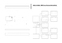
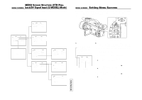
SYSTEM Menu Screen (Shooting mode)
 |
View all JVC GY-DV300REM manuals
Add to My Manuals
Save this manual to your list of manuals |
Page 48 highlights
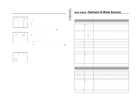
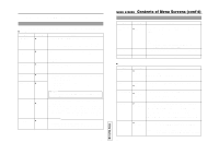
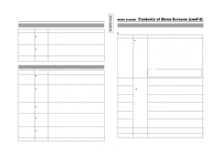
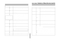
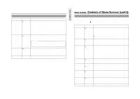
The displayed menu screens of the SYSTEM Menu Screen differ with the shooting mode and the VTR mode. SYSTEM Menu Screen (Shooting mode) In the shooting mode, the SYSTEM Menu Screen consists of two screens (1/2 screen and 2/2 screen). Ⅲ SYSTEM 1/2 screen Item Set Value Contents MIC1 INPUT SEL ● INT XLR Selects whether the built-in microphone or a microphone connected to the MIC 1 input connector should be used. INT : Use this setting when the built-in microphone should be used. XLR : Use this setting when a microphone connected to the MIC 1 input connector should be used. WIND CUT MIC1 ● OFF ON Selects whether or not the wind noise picked up by the internal microphone or a microphone connected to the MIC 1 input connector is reduced. OFF : Not reduced. ON : Reduced. WIND CUT MIC2 ● OFF ON Selects whether or not the wind noise picked up by a microphone connected to the MIC 2 input connector is reduced. OFF : Not reduced. ON : Reduced. +48V MIC1 ● OFF ON To set whether +48 V power should be supplied to a microphone connected to the MIC 1 or MIC 2 input connector. MIC 1 and MIC 2 are set separately. +48V MIC2 ● OFF ON OFF : +48 V power is not supplied. ON : +48 V power is supplied. Use this setting when a phantom microphone is used. Memo: "- - -" is displayed when the MIC1 INPUT SEL item is set to INT, and setting is not possible. AUDIO MODE 32K ● 48K REC MODE ● SP LP Selects the sampling frequency for audio recording (common for CH-1 and CH-2) 32K : Recording is performed with 12-bit, 32 kHz sampling frequency 48K : Recording is performed with 16-bit, 48 kHz sampling frequency * 4 channels are available when the DV format is recorded with 12-bit, 32 kHz audio sampling. The GY-DV300 records audio on the CH-1 and CH-2 channels. The GY-DV300 does not allow after-recording. Selects the recording speed mode. SP : Standard Play recording speed mode. LP : Long Play recording speed mode (recording time is 1.5 times longer than in the SP mode.) 91 TENTATIVE MENU SCREEN Contents of Menu Screens (cont'd) SYSTEM Menu Screens (Shooting mode) (Cont'd) Item LONG PAUSE TIME NEXT PAGE PAGE BACK Set Value 3 MIN ● 30 MIN Contents Selects the time (minutes) before the tape protection mode is engaged when the recording-standby mode or still mode continues. Tape protection mode: Drum rotation stops automatically. When used in a cold environment, this becomes 3 minutes regardless of the setting. 3 MIN : 3 minutes 30 MIN : 30 minutes When used in a cold environment, this becomes 3 minutes regardless of the setting. The SYSTEM [2/2] menu screen appears when the SELECT dial is pressed. The TOP MENU returns when the SELECT dial is pressed. Ⅲ SYSTEM [2/2] Menu Screen Item Set Value Contents FADER ● OFF BLACK Selects whether fade is performed when recording is started and stopped. OFF : No fade. BLACK : Picture fades in from black screen when recording is started; fades out to black screen when recording is stopped. TALLY OFF ● ON Selects whether or not the TALLY lamp lights during recording. OFF : TALLY lamp does not light during recording. ON : TALLY lamp lights during recording HANDLE ZOOM SLOW ● MEDIUM FAST Sets the zoom speed for when the ZOOM lever on the handle section is used. SLOW : Zoom operation is slow MEDIUM : Normal zoom operation speed FAST : Zoom operation is fast DATE REC ● BARS Selects the mode for recording the date and time on the tape. BARS+CAM When the date and time should be recorded on the tape, the TIME/DATE item must be set to DISP+REC on the DISPLAY [2/2] menu screen. Select the style of the time and date with the DISP STYLE item on the DISPLAY [2/2] menu screen. BARS : Recorded when built-in color bar signal is output. BARS+CAM : Recorded when built-in color bar signal and the camera image are output. ASPECT ● 4:3 LETTER Selects the image size of the recorded image. 4:3 : To record with the normal screen size with an aspect ratio of 4:3. LETTER : To record with a LETTER BOX screen with an aspect ratio of 16:9 where the upper and lower part of the image is cut off. 92
-
 1
1 -
2
-
3
-
4
-
5
-
6
-
7
-
8
-
9
-
10
-
11
-
12
-
13
-
14
-
15
-
16
-
17
-
18
-
19
-
20
-
21
-
22
-
23
-
24
-
25
-
26
-
27
-
28
-
29
-
30
-
31
-
32
-
33
-
34
-
35
-
36
-
37
-
38
-
39
-
40
-
41
-
42
-
 43
43 -
 44
44 -
 45
45 -
 46
46 -
 47
47 -
 48
48 -
 49
49 -
 50
50 -
 51
51 -
 52
52 -
 53
53 -
54
-
55
-
56
-
57
 |
 |
