Kenmore 75121 Owners Manual - Page 7
qJ Attach the L BRACKET - installation
 |
View all Kenmore 75121 manuals
Add to My Manuals
Save this manual to your list of manuals |
Page 7 highlights
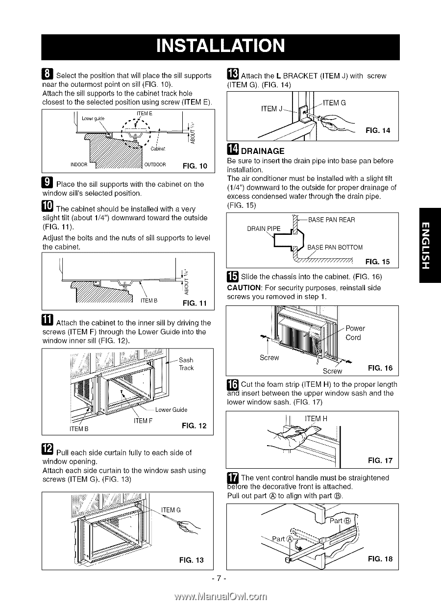
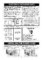
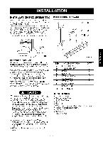
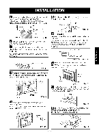
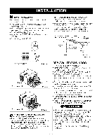
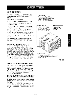
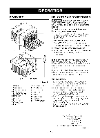
E'_ Select the position that will place the sill supports near the outermost point on sill (FIG. 10). Attach the sill supports to the cabinet track hole closest to the selected position using screw (ITEM E). ITEM E _qJ Attach the L BRACKET (ITEM J) with screw (ITEM G). (FIG. 14) _ jlTEM G FIG. 14 INDOOR Cabinet OUTDOOR FIG. 10 _J_ Place the sill supports with the cabinet on the window sill's selected position. _1_ The cabinet should be installed with a very slight tilt (about 1/4") downward toward the outside (FIG. 11). Adjust the bolts and the nuts of sill supports to level the cabinet. ITEMB .< FIG. 11 _1 Attach the cabinet to the inner sill by driving the screws (ITEM F) through the Lower Guide into the window inner sill (FIG. 12). i!il !iiili!i!i!¸_¸¸i;¸i;_¸;i¸l¸i ¸;!_ TrackSash _ I_?"_ ITEMB _Lower Guide ITEMF FIG. 12 _'! DRAINAGE Be sure to insert the drain pipe into base pan before installation. The air conditioner must be installed with a slight tilt (1/4") downward to the outside for proper drainage of excess condensed water through the drain pipe. (FIG. 15) "_BASE PANREAR DRAIN _OM FIG. 15 _"'_ Slide the chassis into the cabinet. (FIG. 16) CAUTION: For security purposes, reinstall side screws you removed in step 1. Cord Screw Screw FIG. 16 Cut the foam strip (ITEM H) to the proper length insert between the upper window sash and the lower window sash. (FIG. 17) _"_ Pull each side curtain fully to each side of window opening. Attach each side curtain to the window sash using screws (ITEM G). (FIG. 13) FIG. 17 straightened _oThree thevendteccoornattrivoel hfaronndtleismauttsatchbeed. Pull out part (_)to align with part (_. ITEMG FIG. 13 -7- ..--. -_. FIG. 18
-
 1
1 -
 2
2 -
 3
3 -
 4
4 -
 5
5 -
 6
6 -
 7
7 -
 8
8 -
 9
9 -
 10
10 -
 11
11 -
 12
12 -
13
-
14
-
15
-
16
-
17
-
18
-
19
-
20
-
21
-
22
-
23
-
24
-
25
-
26
-
27
-
28
-
29
-
30
-
31
-
32
 |
 |