Konica Minolta C83hc High Chroma AccurioPress C3080/C3080P/C3070/Print C3070L - Page 65
Service port USB 2.0 Type B x 1
 |
View all Konica Minolta C83hc High Chroma manuals
Add to My Manuals
Save this manual to your list of manuals |
Page 65 highlights
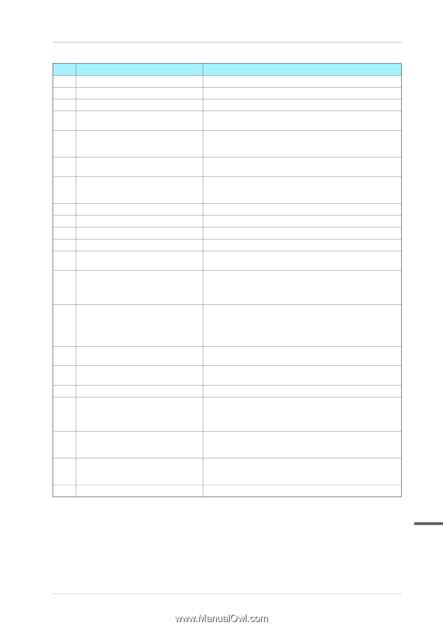
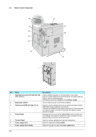
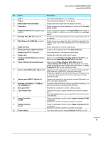
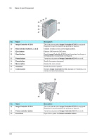
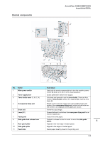
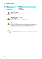
AccurioPress C3080/C3080P/C3070 AccurioPrint C3070L No. Name 8 Tray 1 9 Tray 2 Description Holds 500 sheets (80 g/m2 / 21 lb Bond). Holds 1000 sheets (80 g/m2 / 21 lb Bond). 10 Main body front door handle Pulled to the left to open the main body front door. 11 Front door Opens to allow removal of paper jam or to turn on/off the main power switch. 12 Original Cover OC-511 (Original cover) Opens to place an original on the Original Glass, then closes to (Option) hold it in position. This device cannot be installed on the Printer model. 13 Working Table WT-511 (optional) Provides a convenient workspace for documents before and after copying. 14 Multi Bypass Tray MB-506 (optional) Opens to use copy paper other than that which is loaded in the machine trays. Up to 250 sheets (80 g/m2 / 21 lb Bond) can be loaded. 15 Right side door Opens rightward for removal of paper jam. 16 Waste toner box replacement door Opens to allow replacement of the waste toner box. 17 Output Tray OT-511 (optional) Holds sets output in non-offset or offset mode. 18 Power cord Supplies the main body with electric power. 19 Intelligent Quality Optimizer connec- Used to connect Intelligent Quality Optimizer IQ-501 by ca- tion port ble. (Only with Video Interface Kit VI-511 mounted) 20 Video Interface Kit connection port Used to mount Video Interface Kit VI-509 (optional). * Video Interface Kit VI-509 (optional) is required to connect Image Controller IC-313, Image Controller IC-314, or Image Controller IC-417 to this machine by cable. 21 Service port (USB 3.0/2.0 Type A x 1) Used to connect devices such as an external storage medium (USB flash drive, USB-HDD), keyboard and mouse. This port is available for low-power devices only. Please provide an external supply of power for devices that require a large amount of power. 22 Service port (USB 2.0 Type B x 1) Connect this machine to the computer using a USB cable in order to use it as a local printer. 23 Network port (10Base-T, 100Base- Connected with an Ethernet cable to operate the machine, or to TX, 1000Base-T) use the machine as a network printer/scanner. 24 Dust proof filter Attached for cooling fan in order to keep out dust. 25 Lock release lever Pressed to the back to open downward for removal of paper jam. The lock release lever can be reached from the optional device in the left side. 26 Image Controller IC-605 This is the installation position when Image Controller IC-605 is equipped. Required to use this machine as a printer or scanner. 27 Image Controller IC-417 This is the installation position when Image Controller IC-417 is equipped. Required to use this machine as a printer or scanner. 28 Power switch Turns the main power of Image Controller IC-417 on or off. 5 5-4
-
 1
1 -
2
-
3
-
4
-
5
-
6
-
7
-
8
-
9
-
10
-
11
-
12
-
13
-
14
-
15
-
16
-
17
-
18
-
19
-
20
-
21
-
22
-
23
-
24
-
25
-
26
-
27
-
28
-
29
-
30
-
31
-
32
-
33
-
34
-
35
-
36
-
37
-
38
-
39
-
40
-
41
-
42
-
43
-
44
-
45
-
46
-
47
-
48
-
49
-
50
-
51
-
52
-
53
-
54
-
55
-
56
-
57
-
58
-
59
-
 60
60 -
 61
61 -
 62
62 -
 63
63 -
 64
64 -
 65
65 -
 66
66 -
 67
67 -
 68
68 -
 69
69 -
 70
70 -
71
 |
 |