LG 42LB5RT Owner's Manual - Page 25
Connecting with a HDMI to DVI cable
 |
View all LG 42LB5RT manuals
Add to My Manuals
Save this manual to your list of manuals |
Page 25 highlights
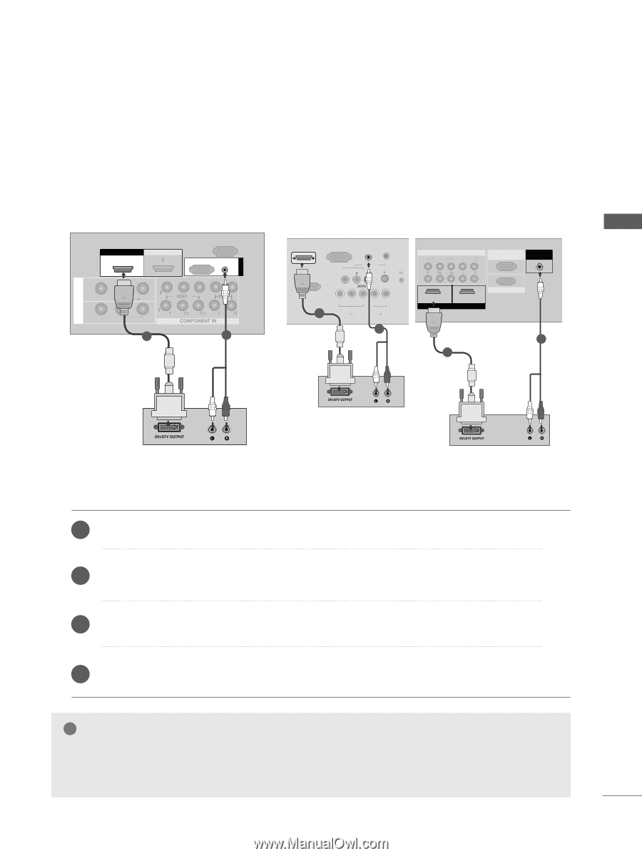
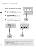
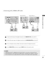
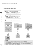
EXTERNAL EQUIPMENT SETUP Connecting with a HDMI to DVI cable COMPONENT IN VIDEO AUDIO 1 RS-232C IN (CONTROL&SERVICE) AUDIO IN (RGB/DVI) AV OUT AV IN HHDDMMI DI/DVVI ININ 1 2 HDMI IN 1 HDMI/DVI IN 2 HDMI IN RS-232C IN (CONTROL) RGB(PC) AUDIO (RGB/DVI) IN 1 AV VIDEO L/MONO AUDIO R OUT VARIABLE AUDIO OUT 1 2 RGB IN RGB IN (PC) Only 22LG3*** HDMI/DVI IN ANTENNA IN AUDIO RGB(PC) IN (RGB/DVI) IN ANTENNA AV IN VIDEO AUDIO S-VIDEO H/P RS-232C IN (CONTROL&SERVICE) 1 LR Y PB PR L R VIDEO AUDIO COMPONENT IN Only 32PC5*** COMPONENT IN VIDEO AUDIO 1 2 1 HDMI/DVI IN 2 HDMI IN RS-232C IN (CONTROL&SERVICE) RGB IN (PC) AUDIO IN (RGB/DVI) 2 2 1 AV OUT AV IN ANTENNA IN COMPONENT IN VIDEO AUDIO 1 2 1 HDMI/DVI IN 2 HDMI IN RS-232C IN (CONTROL&SERVICE) AUDIO IN (RGB/DVI) RGB IN (PC) AV OUT AV IN ANTENNA IN 1 Connect the DVI output of the digital set-top box to the HDMI/DVI IN 1 jack on the TV. 2 Connect the audio output of the digital set-top box to the AUDIO(RGB/DVI) jack on the TV. 3 Turn on the digital set-top box. (Refer to the owner's manual for the digital set-top box.) 4 Select HDMI1/DVI input source using the INPUT button on the remote control. ! NOTE G HDMI2(Except 22LG3***), HDMI3(Only 32/37/42/47/52LG5***) source does not support DVI source. G If the Set-Top Box has a DVI output and no HDMI output, a separated audio connection is necessary. G If the Set-Top Box does not support Auto DVI, you need to set the output resolution appropriately. 23
-
 1
1 -
2
-
3
-
4
-
5
-
6
-
7
-
8
-
9
-
10
-
11
-
12
-
13
-
14
-
15
-
16
-
17
-
18
-
19
-
 20
20 -
 21
21 -
 22
22 -
 23
23 -
 24
24 -
 25
25 -
 26
26 -
 27
27 -
 28
28 -
 29
29 -
 30
30 -
31
-
32
-
33
-
34
-
35
-
36
-
37
-
38
-
39
-
40
-
41
-
42
-
43
-
44
-
45
-
46
-
47
-
48
-
49
-
50
-
51
-
52
-
53
-
54
-
55
-
56
-
57
-
58
-
59
-
60
-
61
-
62
-
63
-
64
-
65
-
66
-
67
-
68
-
69
-
70
-
71
-
72
-
73
-
74
-
75
-
76
-
77
-
78
-
79
-
80
-
81
-
82
-
83
-
84
-
85
-
86
-
87
-
88
-
89
-
90
-
91
-
92
-
93
-
94
-
95
-
96
-
97
-
98
-
99
-
100
-
101
-
102
-
103
-
104
-
105
-
106
-
107
-
108
-
109
-
110
-
111
-
112
-
113
-
114
-
115
-
116
-
117
-
118
 |
 |