LG DU-37LZ30 Owners Manual - Page 12
NOTE: All cables shown are not included with the TV, Connection Option 1, Connection Option 2, Cable - service manual
 |
View all LG DU-37LZ30 manuals
Add to My Manuals
Save this manual to your list of manuals |
Page 12 highlights
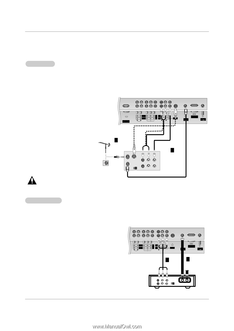
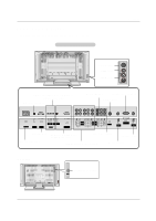
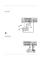
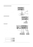
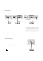
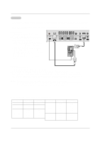
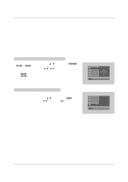
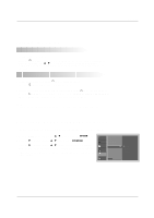
Installation NOTE: All cables shown are not included with the TV VCR Setup - To avoid picture noise (interference), leave an adequate distance between the VCR and TV - Typically a frozen still picture from a VCR. If the 4:3 picture format is used; the fixed images on the sides of the screen may remain visible on the screen. Connection Option 1 Set VCR output switch to 3 or 4 and then tune TV to the same channel number. Connection Option 2 1. Connect the audio and video cables from the VCR's output jacks to the TV input jacks, as shown in the figure. When connecting the TV to VCR, match the jack colors (Video = yellow, Audio Left = white, and Audio Right = red). If you connect an S-VIDEO output from VCR to the S-VIDEO input, the picture quality is improved; compared to connecting a regular VCR to the Video input. 2. Insert a video tape into the VCR and press PLAY on the VCR. (Refer to the VCR owner's manual.) 3. Select the input source with using the TV/VIDEO button on the remote control. (If connected to A/V INPUT 1, select Video 1 input source) Do not connect to both Video and S-Video at the same time. RGB INPUT (PC/DTV INPUT) COMPONENT 2 COMPONENT 1 R L DVD /DTV INPUT MONITOR OUTPUT A/V INPUT1 (MONO) R AUDIO L VIDEO AUDIO INPUT VIDEO INPUT S-VIDEO Antenna1 DVI INPUT (PC/DTV INPUT) Antenna 2 1 ANT IN ANT OUT S-VIDEO OUT OUTPUT (R) AUDIO (L) SWITCH 3 4 IN VIDEO 2 VCR Cable TV Setup - After subscribing to a cable TV service from a local provider and installing a converter, you can watch cable TV programming. The TV cannot display TV programming unless a TV tuner device or cable TV converter box is connected to the TV. - For further information regarding cable TV service, contact your local cable TV service provider(s). Connection Option 1 1. Select 3 or 4 with channel switch on cable box. 2. Tune the TV channel to the same selected output channel on cable box. 3. Select channels at the cable box or with the cable box remote control. Connection Option 2 1. Connect the audio and video cables from the Cable Box's output jacks to the TV input jacks, as shown in the figure. When connecting the TV to a Cable Box, match the jack colors (Video = yellow, Audio Left = white, and Audio Right = red). 2. Select the input source with using the TV/VIDEO button on the remote control. (If connected to A/V INPUT 1, select Video 1 input source) 3. Select your desired channel with the remote control for cable box. COMPONENT 2 COMPONENT 1 R L DVD /DTV INPUT MONITOR OUTPUT A/V INPUT1 (MONO) R AUDIO L VIDEO AUDIO INPUT VIDEO INPUT S-VIDEO 2 Antenna1 DVI INPUT (PC/DTV INPUT) Antenna 2 1 (R) AUDIO (L) VIDEO TV VCR OUTPUT SWITCH 34 RF Cable Cable Box 12
-
 1
1 -
2
-
3
-
4
-
5
-
6
-
 7
7 -
 8
8 -
 9
9 -
 10
10 -
 11
11 -
 12
12 -
 13
13 -
 14
14 -
 15
15 -
 16
16 -
 17
17 -
18
-
19
-
20
-
21
-
22
-
23
-
24
-
25
-
26
-
27
-
28
-
29
-
30
-
31
-
32
-
33
-
34
-
35
-
36
-
37
-
38
-
39
-
40
-
41
-
42
-
43
-
44
-
45
-
46
-
47
-
48
 |
 |