Lantronix SLC 16 Lantronix SLC - User Guide - Page 27
Physical Installation, Connecting to Device Ports
 |
View all Lantronix SLC 16 manuals
Add to My Manuals
Save this manual to your list of manuals |
Page 27 highlights
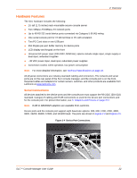
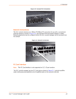
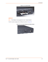
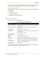
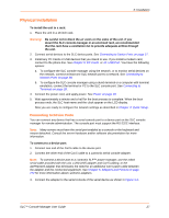
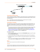
3: Installation Physical Installation To install the unit in a rack: 1. Place the unit in a 19-inch rack. Warning: Be careful not to block the air vents on the sides of the unit. If you mount the SLC console manager in an enclosed rack, we recommended that the rack have a ventilation fan to provide adequate airflow through the unit. 2. Connect serial devices to the SLC device ports. See Connecting to Device Ports on page 27. 3. Install any PC Cards or USB devices that you intend to use. If you install a modem card, connect to the phone line. See Chapter 9: PC Cards or 10: USB Port. You have the following options: a. To configure the SLC console manager using the network, or to monitor serial devices on the network, connect at least one SLC network port to a network. See Connecting to Network Ports on page 28. b. To configure the SLC console manager using a dumb terminal or a computer with terminal emulation, connect the terminal or PC to the SLC console port. See Connecting to Terminals on page 28. 4. Connect the power cord, and apply power. See Power on page 28. 5. Wait approximately a minute and a half for the boot process to complete. When the boot process ends, the SLC host name and the clock appear on the LCD display. Now you are ready to configure the network settings as described in Chapter 4: Quick Setup . Connecting to Device Ports You can connect any device that has a serial console port to a device port on the SLC console manager for remote administration. The console port must support the RS-232C interface. Note: Many servers must have the serial port enabled as a console or the keyboard and mouse detached. Consult the server hardware and/or software documentation for more information. To connect to a device port: 1. Connect one end of the Cat 5 cable to the device port. 2. Connect the other end of the Cat 5 cable to a Lantronix serial console adapter. Note: To connect a device port to a Lantronix SLP™ power manager, use the rolled serial cable provided with the unit, a 200.2225 adapter and Cat 5 cabling, or the ADP010104 adapter that eliminates the need for an additional Cat 5 patch cable between the adapter and the connected equipment. See Chapter 5: Adapters and Pinouts on page 272 for more information about Lantronix adapters. 3. Connect the adapter to the serial console of the serial device as shown in Figure 3-3. SLC™ Console Manager User Guide 27
-
 1
1 -
2
-
3
-
4
-
5
-
6
-
7
-
8
-
9
-
10
-
11
-
12
-
13
-
14
-
15
-
16
-
17
-
18
-
19
-
20
-
21
-
 22
22 -
 23
23 -
 24
24 -
 25
25 -
 26
26 -
 27
27 -
 28
28 -
 29
29 -
 30
30 -
 31
31 -
 32
32 -
33
-
34
-
35
-
36
-
37
-
38
-
39
-
40
-
41
-
42
-
43
-
44
-
45
-
46
-
47
-
48
-
49
-
50
-
51
-
52
-
53
-
54
-
55
-
56
-
57
-
58
-
59
-
60
-
61
-
62
-
63
-
64
-
65
-
66
-
67
-
68
-
69
-
70
-
71
-
72
-
73
-
74
-
75
-
76
-
77
-
78
-
79
-
80
-
81
-
82
-
83
-
84
-
85
-
86
-
87
-
88
-
89
-
90
-
91
-
92
-
93
-
94
-
95
-
96
-
97
-
98
-
99
-
100
-
101
-
102
-
103
-
104
-
105
-
106
-
107
-
108
-
109
-
110
-
111
-
112
-
113
-
114
-
115
-
116
-
117
-
118
-
119
-
120
-
121
-
122
-
123
-
124
-
125
-
126
-
127
-
128
-
129
-
130
-
131
-
132
-
133
-
134
-
135
-
136
-
137
-
138
-
139
-
140
-
141
-
142
-
143
-
144
-
145
-
146
-
147
-
148
-
149
-
150
-
151
-
152
-
153
-
154
-
155
-
156
-
157
-
158
-
159
-
160
-
161
-
162
-
163
-
164
-
165
-
166
-
167
-
168
-
169
-
170
-
171
-
172
-
173
-
174
-
175
-
176
-
177
-
178
-
179
-
180
-
181
-
182
-
183
-
184
-
185
-
186
-
187
-
188
-
189
-
190
-
191
-
192
-
193
-
194
-
195
-
196
-
197
-
198
-
199
-
200
-
201
-
202
-
203
-
204
-
205
-
206
-
207
-
208
-
209
-
210
-
211
-
212
-
213
-
214
-
215
-
216
-
217
-
218
-
219
-
220
-
221
-
222
-
223
-
224
-
225
-
226
-
227
-
228
-
229
-
230
-
231
-
232
-
233
-
234
-
235
-
236
-
237
-
238
-
239
-
240
-
241
-
242
-
243
-
244
-
245
-
246
-
247
-
248
-
249
-
250
-
251
-
252
-
253
-
254
-
255
-
256
-
257
-
258
-
259
-
260
-
261
-
262
-
263
-
264
-
265
-
266
-
267
-
268
-
269
-
270
-
271
-
272
-
273
-
274
-
275
-
276
-
277
-
278
-
279
-
280
-
281
-
282
-
283
-
284
-
285
-
286
-
287
-
288
-
289
-
290
-
291
-
292
-
293
-
294
-
295
-
296
-
297
-
298
-
299
 |
 |