Lenovo ThinkCentre Chromebox Hardware Maintenance Manual (HMM) - ThinkCentre C - Page 75
Replacing the power button board
 |
View all Lenovo ThinkCentre Chromebox manuals
Add to My Manuals
Save this manual to your list of manuals |
Page 75 highlights
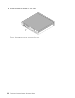
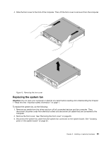
5. Position a new system board frame on the system board so that the two holes on the system board frame are aligned with the standoffs on the system board. Slide the system board frame as shown until the two screw holes 1 are aligned with the corresponding mounting studs on the system board. Figure 18. Installing the system board frame 6. Install the two screws to secure the system board frame. Figure 19. Installing the screws to secure the system board frame What to do next: • To work with another piece of hardware, go to the appropriate section. • To complete the installation or replacement, go to "Completing the parts replacement" on page 81. Replacing the power button board Attention: Do not open your computer or attempt any repair before reading and understanding the Chapter 1 "Read this first: Important safety information" on page 1. To replace the power button board, do the following: Chapter 9. Installing or replacing hardware 69
-
 1
1 -
2
-
3
-
4
-
5
-
6
-
7
-
8
-
9
-
10
-
11
-
12
-
13
-
14
-
15
-
16
-
17
-
18
-
19
-
20
-
21
-
22
-
23
-
24
-
25
-
26
-
27
-
28
-
29
-
30
-
31
-
32
-
33
-
34
-
35
-
36
-
37
-
38
-
39
-
40
-
41
-
42
-
43
-
44
-
45
-
46
-
47
-
48
-
49
-
50
-
51
-
52
-
53
-
54
-
55
-
56
-
57
-
58
-
59
-
60
-
61
-
62
-
63
-
64
-
65
-
66
-
67
-
68
-
69
-
 70
70 -
 71
71 -
 72
72 -
 73
73 -
 74
74 -
 75
75 -
 76
76 -
 77
77 -
 78
78 -
 79
79 -
 80
80 -
81
-
82
-
83
-
84
-
85
-
86
-
87
-
88
-
89
-
90
-
91
-
92
-
93
-
94
-
95
-
96
-
97
-
98
-
99
-
100
-
101
-
102
-
103
-
104
-
105
-
106
-
107
-
108
-
109
-
110
-
111
-
112
 |
 |
