Lenovo ThinkCentre E51 Hardware Maintenance Manual - Page 139
Replacing the system board, Machine types 8293
 |
View all Lenovo ThinkCentre E51 manuals
Add to My Manuals
Save this manual to your list of manuals |
Page 139 highlights
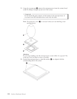
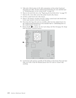
10. Position the system board so that the screws holes are aligned and install the system board screws. 11. Install the hard disk drive. Make sure to route the power supply cable for the system board underneath the hard disk drive. See "Replacing the hard disk drive" on page 150. 12. Reconnect all other power supply cables to the system board and the drives. Make sure the cables are correctly routed. See the system board illustration for your machine type at "Identifying parts on the system board" on page 123. 13. Replace the drive bay assembly. See "Removing and replacing the drive bay assembly" on page 127. 14. Go to "Completing the FRU replacement" on page 154. Replacing the system board The procedure for replacing the system board is different depending on the machine type of the computer. Note: When replacing the system board, a new retention bracket for the microprocessor heat sink is required. Make sure you have a new retention bracket before beginning this procedure. Machine types 8293, 8294, 8295, 8473, 8474, 8710, 8711, 8773, 8774, 8778, 8779, 8818, 8819, 9217, 9218, and 9219 1. Remove the cover. See "Removing the cover" on page 121. 2. Lift the fan duct off the heat sink fan. 3. Remove any adapter cards installed in the PCI connectors. See "Replacing a PCI adapter" on page 129. 4. Remove the drive bay assembly. See "Removing and replacing the drive bay assembly" on page 127. 5. Take note of the location of all cable connections on the system board and disconnect all cables. See the system board illustration for your machine type at "Identifying parts on the system board" on page 123. 6. Remove the hard disk drive. See "Replacing the hard disk drive" on page 150. 7. Remove the screws that secure the system board to the chassis. 8. Lift the system board out of the chassis. 9. Remove the memory modules from the failing system board and install them in the same location on the new system board. 10. Disconnect the heat sink and fan assembly cable from the system board. See the system board illustration for your machine type at "Identifying parts on the system board" on page 123. Chapter 9. Replacing FRUs (Desktop computers) 133
-
 1
1 -
2
-
3
-
4
-
5
-
6
-
7
-
8
-
9
-
10
-
11
-
12
-
13
-
14
-
15
-
16
-
17
-
18
-
19
-
20
-
21
-
22
-
23
-
24
-
25
-
26
-
27
-
28
-
29
-
30
-
31
-
32
-
33
-
34
-
35
-
36
-
37
-
38
-
39
-
40
-
41
-
42
-
43
-
44
-
45
-
46
-
47
-
48
-
49
-
50
-
51
-
52
-
53
-
54
-
55
-
56
-
57
-
58
-
59
-
60
-
61
-
62
-
63
-
64
-
65
-
66
-
67
-
68
-
69
-
70
-
71
-
72
-
73
-
74
-
75
-
76
-
77
-
78
-
79
-
80
-
81
-
82
-
83
-
84
-
85
-
86
-
87
-
88
-
89
-
90
-
91
-
92
-
93
-
94
-
95
-
96
-
97
-
98
-
99
-
100
-
101
-
102
-
103
-
104
-
105
-
106
-
107
-
108
-
109
-
110
-
111
-
112
-
113
-
114
-
115
-
116
-
117
-
118
-
119
-
120
-
121
-
122
-
123
-
124
-
125
-
126
-
127
-
128
-
129
-
130
-
131
-
132
-
133
-
 134
134 -
 135
135 -
 136
136 -
 137
137 -
 138
138 -
 139
139 -
 140
140 -
 141
141 -
 142
142 -
 143
143 -
 144
144 -
145
-
146
-
147
-
148
-
149
-
150
-
151
-
152
-
153
-
154
-
155
-
156
-
157
-
158
-
159
-
160
-
161
-
162
-
163
-
164
-
165
-
166
-
167
-
168
-
169
-
170
-
171
-
172
-
173
-
174
-
175
-
176
-
177
-
178
-
179
-
180
-
181
-
182
-
183
-
184
-
185
-
186
-
187
-
188
-
189
-
190
-
191
-
192
-
193
-
194
-
195
-
196
-
197
-
198
-
199
-
200
-
201
-
202
-
203
-
204
-
205
-
206
-
207
-
208
-
209
-
210
-
211
-
212
-
213
-
214
-
215
-
216
-
217
-
218
-
219
-
220
-
221
-
222
-
223
-
224
-
225
-
226
-
227
-
228
-
229
-
230
-
231
-
232
-
233
-
234
-
235
-
236
-
237
-
238
-
239
-
240
-
241
-
242
-
243
-
244
-
245
-
246
-
247
-
248
-
249
-
250
-
251
-
252
-
253
-
254
-
255
-
256
-
257
-
258
-
259
-
260
-
261
-
262
-
263
-
264
-
265
-
266
-
267
-
268
-
269
-
270
-
271
-
272
-
273
-
274
-
275
-
276
-
277
-
278
-
279
-
280
-
281
-
282
-
283
-
284
-
285
-
286
-
287
-
288
-
289
-
290
-
291
-
292
-
293
-
294
-
295
-
296
-
297
-
298
-
299
-
300
-
301
-
302
-
303
-
304
-
305
-
306
-
307
-
308
-
309
-
310
-
311
-
312
-
313
-
314
-
315
-
316
-
317
-
318
-
319
-
320
-
321
-
322
-
323
-
324
-
325
-
326
-
327
-
328
-
329
-
330
-
331
-
332
-
333
-
334
-
335
-
336
-
337
-
338
-
339
-
340
-
341
-
342
-
343
-
344
-
345
-
346
-
347
-
348
-
349
-
350
 |
 |
