Lenovo ThinkCentre M51 Hardware Maintenance Manual - Page 147
connectors.
 |
View all Lenovo ThinkCentre M51 manuals
Add to My Manuals
Save this manual to your list of manuals |
Page 147 highlights
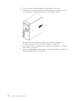
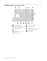
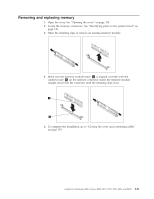
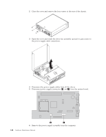
Removing and replacing memory 1. Open the cover. See "Opening the cover" on page 138. 2. Locate the memory connectors. See "Identifying parts on the system board" on page 140. 3. Open the retaining clips to remove an existing memory module. 4. Make sure the memory module notch 1 is aligned correctly with the connector key 2 on the memory connector. Insert the memory module straight down into the connector until the retaining clips close. 5. To complete the installation, go to "Closing the cover and connecting cables" on page 159. Chapter 10. Replacing FRUs (Types 8098, 8171, 8172, 8173, 8424, and 8425) 141
-
 1
1 -
2
-
3
-
4
-
5
-
6
-
7
-
8
-
9
-
10
-
11
-
12
-
13
-
14
-
15
-
16
-
17
-
18
-
19
-
20
-
21
-
22
-
23
-
24
-
25
-
26
-
27
-
28
-
29
-
30
-
31
-
32
-
33
-
34
-
35
-
36
-
37
-
38
-
39
-
40
-
41
-
42
-
43
-
44
-
45
-
46
-
47
-
48
-
49
-
50
-
51
-
52
-
53
-
54
-
55
-
56
-
57
-
58
-
59
-
60
-
61
-
62
-
63
-
64
-
65
-
66
-
67
-
68
-
69
-
70
-
71
-
72
-
73
-
74
-
75
-
76
-
77
-
78
-
79
-
80
-
81
-
82
-
83
-
84
-
85
-
86
-
87
-
88
-
89
-
90
-
91
-
92
-
93
-
94
-
95
-
96
-
97
-
98
-
99
-
100
-
101
-
102
-
103
-
104
-
105
-
106
-
107
-
108
-
109
-
110
-
111
-
112
-
113
-
114
-
115
-
116
-
117
-
118
-
119
-
120
-
121
-
122
-
123
-
124
-
125
-
126
-
127
-
128
-
129
-
130
-
131
-
132
-
133
-
134
-
135
-
136
-
137
-
138
-
139
-
140
-
141
-
 142
142 -
 143
143 -
 144
144 -
 145
145 -
 146
146 -
 147
147 -
 148
148 -
 149
149 -
 150
150 -
 151
151 -
 152
152 -
153
-
154
-
155
-
156
-
157
-
158
-
159
-
160
-
161
-
162
-
163
-
164
-
165
-
166
-
167
-
168
-
169
-
170
-
171
-
172
-
173
-
174
-
175
-
176
-
177
-
178
-
179
-
180
-
181
-
182
-
183
-
184
-
185
-
186
-
187
-
188
-
189
-
190
-
191
-
192
-
193
-
194
-
195
-
196
-
197
-
198
-
199
-
200
-
201
-
202
-
203
-
204
-
205
-
206
-
207
-
208
-
209
-
210
-
211
-
212
-
213
-
214
-
215
-
216
-
217
-
218
-
219
-
220
-
221
-
222
-
223
-
224
-
225
-
226
-
227
-
228
-
229
-
230
-
231
-
232
-
233
-
234
-
235
-
236
-
237
-
238
-
239
-
240
-
241
-
242
-
243
-
244
-
245
-
246
-
247
-
248
-
249
-
250
-
251
-
252
-
253
-
254
-
255
-
256
-
257
-
258
-
259
-
260
-
261
-
262
-
263
-
264
-
265
-
266
-
267
-
268
-
269
-
270
-
271
-
272
-
273
-
274
-
275
-
276
-
277
-
278
-
279
-
280
-
281
-
282
-
283
-
284
-
285
-
286
-
287
-
288
-
289
-
290
-
291
-
292
-
293
-
294
-
295
-
296
-
297
-
298
-
299
-
300
-
301
-
302
-
303
-
304
-
305
-
306
-
307
-
308
-
309
-
310
-
311
-
312
-
313
-
314
-
315
-
316
-
317
-
318
-
319
-
320
-
321
-
322
-
323
-
324
-
325
-
326
-
327
-
328
-
329
-
330
-
331
-
332
-
333
-
334
-
335
-
336
-
337
-
338
-
339
-
340
-
341
-
342
-
343
-
344
-
345
-
346
-
347
-
348
-
349
-
350
-
351
-
352
 |
 |

Removing
and
replacing
memory
1.
Open
the
cover.
See
“Opening
the
cover”
on
page
138.
2.
Locate
the
memory
connectors.
See
“Identifying
parts
on
the
system
board”
on
page
140.
3.
Open
the
retaining
clips
to
remove
an
existing
memory
module.
4.
Make
sure
the
memory
module
notch
±1²
is
aligned
correctly
with
the
connector
key
±2²
on
the
memory
connector.
Insert
the
memory
module
straight
down
into
the
connector
until
the
retaining
clips
close.
5.
To
complete
the
installation,
go
to
“Closing
the
cover
and
connecting
cables”
on
page
159.
Chapter
10.
Replacing
FRUs
(Types
8098,
8171,
8172,
8173,
8424,
and
8425)
141